Portal > SmartBuild
SmartBuild is a web-based configuration tool used to configure, program, and monitor aspects of the PINpoint System. Utilizing its many tabs, customers can configure the Lines, Stations, and Devices. They can also add logic for Andon and products and monitor connectivity between devices.
The SmartBuild interface is accessed by clicking the Portal > SmartBuild button.
Portal > SmartBuild > Hardware
The Hardware page of the SmartBuild interface facilitates adding your production lines and their various devices to PINpoint. As well, it enables you to create Events and Buttons that can be used in conjunction with Stations and BigScreens.
Hardware Page Definitions
The following definitions summarize concepts you will encounter in this section.
Table 2: Hardware page definitions
|
Term |
Definition |
|---|---|
|
BigScreen |
A BigScreen is PINpoint software used to display visual indications of the line status and production metric. |
|
Button |
A button is created in Hardware and is then shown on the SmartScreen Client. When pushed the status changes and an Event is fired. |
|
Event |
An Event describes something that happens in the PINpoint system which can then be utilized with notifications. |
|
Station |
A Station is a location on the Line where a qualified Operator performs work on a Product according to the Process Steps set up there. The Station communicates status and problems between the Client and PINpoint, and communicates them to the Operator and other people as required by the Notifications set up for that Station. |
Lines are the fundamental organizing principle in PINpoint. In almost every aspect, Lines are the place where the elements are brought together, organized, and put to work producing, tracking, and monitoring Build Items.
1.If you are not already in the SmartBuild interface, click on the Portal > SmartBuild button. The SmartBuild interface opens.
2.On the SmartBuild panel, select Hardware. The Hardware workspace opens and displays your facilities.
3.Expand the facility folder to view the Lines folder.
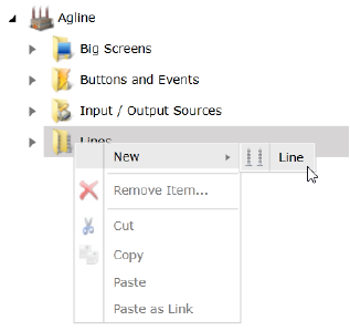
4.Right-click the Lines folder and select New > Line.
Figure 5: Select New Line

The New Line dialog opens.
5.Enter a unique name for the new Line and click OK. The new Line is created and appears in the hierarchy of the Lines folder.
6.Click the Save button located above the Details pane to save the new Line in the system.
Optionally, you may change the following settings in the Details pane:
•Line Name: This is the name of the Line as it appears in SmartBuild and is supplied at the time it is created. You can type in this field to change the Line’s name.
•Node Name: This is the name used by the report database. By default, it is identical to the Line Name; however, you can enter a different name if one is required for reporting purposes.
•Part Hist Days: This is the number of days back that SmartScreen will search the database to determine if a serial number has already been used. If your serial numbers do not repeat, you can safely set this value to "0". The default value is 90 days. To change the value, type a different number in the field, or use the arrow buttons to raise and lower the number by increments of one day.
•Scan Override: This is the unique identification tag used in the database, shown to facilitate database queries. The default value is 0. Type a different value in the field to represent the tag.
•SN Repeat: When checked, this control allows serial numbers to repeat. By default, this is unchecked and the value is false. To set it true and use SN Repeat, place a check in the box.
7.Click the Save button to save any changes you have made in the Details pane.
Creating a new Station on the Line
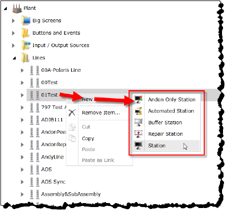
The following instructions apply for all Stations types (Andon Only, Automated, Buffer, Repair, and general Stations).
1.Click the folder of your new Line to make it active.
2.Right-click the Line and select New > Station. The New Station dialog opens.
Figure 6: Create new Station
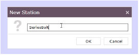
3.Enter a name for the new Station and click OK. The name for the Station must be unique in the Line.
Figure 7: New Station dialog
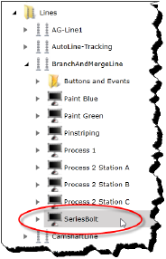
The new Station is created and appears in the hierarchy of the your new Line.
Figure 8: New Station in Line hierarchy
4.Click the Save button located above the Details pane to save the new Station in the system.
5.When the Station is saved, it must be configured. Refer to the table Heading3.
6.Click the Save button to save any changes you have made in the Details pane.
Creating a new Station Configuration
The following instructions apply for all Stations types (Andon Only, Automated, Buffer, Repair, and general Stations).
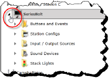
1.Click the folder of your new Station to expand its hierarchy.
Figure 9: Station hierarchy expanded
2.Click the Station Configs item to make it active.
3.Right-click the Station Configs item and select New > Station Config.
Figure 10: Create new Station Config
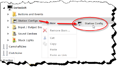
The New Station Config dialog opens.
4.Enter a unique name for the new Station Configuration and click OK. The new Station Configuration is created and appears in the hierarchy of Station Configs.
5.Click the Save button located above the Details pane to save the new station in the system.
6.When the Station Configuration is saved, its attributes must be set. Refer to the table Heading3.
Creating Stack Lights and Sound Devices
When you create Stack Light Devices and Sound Devices in the PINpoint system, what you are actually doing is creating virtual mirrors of actual physical devices in your production facility, and instructing PINpoint on how to communicate with them. Once created, Stack Light Devices and Sound Devices become available in the Notifications page to be associated with Events and Buttons.
Both Events and Buttons can have configurations that enable them to affect Stack Lights and Sound Devices.
About Stack Lights
A Stack Light is associated with a particular station on the line. It may also feature a loudspeaker. Loudspeakers may also be entirely separate devices, as, for example, pole-mounted units accompanying a station. In either case, the Sound Device is created, configured, and actuated separately from the Stack Light.
A Stack Light being controlled by the PINpoint Device Bridge (a service installed on the computer to which the Stack Light is connected) has the following properties:
•The green light is on by default.
•The green, red, and yellow lights cannot be on at the same time: only one of the three can be on at a time.
•When a red or yellow light is turned on, the green light will turn off.
When the Stack Light is first plugged in and connects to the Device Bridge, all the lights will brink. Once it has successfully connected, the following behaviors will indicate the status of the Stack Light’s connectivity:
•Green solid: the Device Bridge is connected to the Data Manager
•Green and red flashing: the Device Bridge was connected to the Data Manager but has since lost connection
•No lights: the Device Bridge has never connected to the Data Manager
Creating a Stack Light
A Stack Light Device must be associated with a Station. It cannot be associated with a Line or a parent facility.
To create and configure a Stack Light Device, follow these steps.
1.If you are not already in the SmartBuild interface, click on the Portal > SmartBuild button. The SmartBuild interface opens.
2.On the SmartBuild panel, select Hardware. The Hardware workspace opens and displays your facilities.
3.Expand the facility you want to work with. The available Lines are displayed.
4.Expand the Line you want to work with. The available Stations are displayed.
5.Expand the Station where you want to create the Stack Light Device.
6.Click on Stack Lights to make it active.
7.Right-click Stack Lights and select New > Stack Light Device. The New Stack Light Device dialog opens.
Figure 17: Add New Stack Light
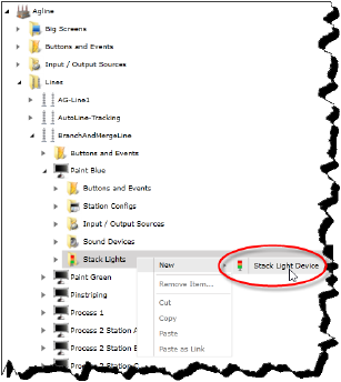
8.Type a name for the Stack Light and click OK.
NoteIt is suggested you enter a name associated with its Station so that it can be easily identified in lists of Stations elsewhere in PINpoint.
The new Stack Light Device is displayed in the Stack Lights hierarchy and the Details pane populates with the Stack Light Device’s configurable attributes.
Figure 18: Stack Light Device Details
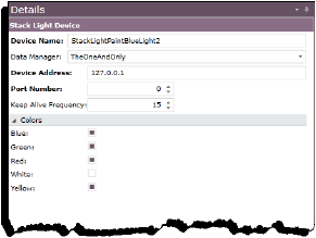
9.Configure the following attributes:
Refer to the table Heading3.
10.When you have completed configuring the Stack Light, click Save.
Creating a Sound Device
A Sound Device must be associated with a Station. It cannot be associated with a Line or a parent facility.
To create and configure a Sound Device, follow these steps.
1.If you are not already in the SmartBuild interface, click on the Portal > SmartBuild button. The SmartBuild interface opens.
2.On the SmartBuild panel, select Hardware. The Hardware workspace opens and displays your facilities.
3.Expand the facility you want to work with. The available Lines are displayed.
4.Expand the Line you want to work with. The available Stations are displayed.
5.Expand the Station where you want to create the Sound Device.
6.Click on Sound Devices to make it active.
7.Right-click Sound Devices and select New > Sound Device. The New Sound Device dialog opens.
Figure 19: Add New Sound Device
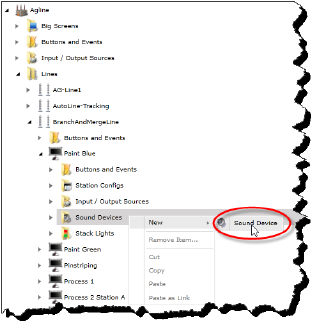
8.Type a name for the Sound Device and click OK.
NoteIt is suggested you enter a name associated with its Station so that it can be easily identified in lists of Stations elsewhere in PINpoint.
The new Sound Device is displayed in the Sound Devices hierarchy and the Details pane populates with the Stack Light Device’s configurable attributes.
Figure 20: Sound Device Details
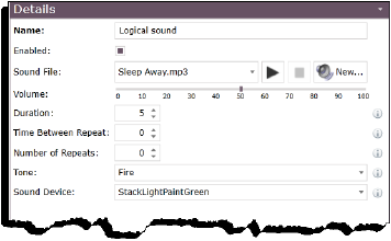
9.Configure the following attributes:
Refer to the table Heading3.
10.When you have completed configuring the Sound Device, click Save.
Input / Output Sources are various devices that can be added to a station to communicate data about the job to the OPC, and in some cases communicate data about the job back from it. To use such devices in conjunction with PINpoint, PINpoint has to be made aware of their existence and network location and configured to use them. This section explains how to do that for a wide variety of supported devices.
Table 3: Default devices for use in PINpoint
|
Network Serial Input Source |
|
Pick Light Input Source |
|
Serial Barcode Scanner Input Source |
|
List Select Input Source |
|
OPC Generic Tag Item Input Source |
|
Loftware Print Document |
|
Fastening Input Sources |
|
Open Protocol Fastening Tool Input Source |
|
Positional Fastening Tool Input Source |
|
Stanely Wireless Wrench CA Series |
|
Desoutter cp CVI PC4 Serial |
|
OPC Fastening Input Source |
|
OPC Hybrid Desoutter CP CVI PC4 Serial |
|
Aimco UEC-4500 Serial |
|
Acradyne IEC Standard Serial |
|
Tester Input Source |
|
Hosted Tester Device |
|
OPC Tester Device |
|
Tester Device |
|
Banner Omni P4 Device |
|
Sentinel C28 Tester Device |
|
Broadcast Tester Device |
|
Keyence Device |
|
Cognex Device |
Creating a Network Serial Input Source
To create a Network Serial Input Source, follow these steps.
1.If you are not already in the SmartBuild interface, click on the Portal > SmartBuild button. The SmartBuild interface opens.
2.On the SmartBuild panel, select Hardware. The Hardware workspace opens and displays your facilities.
3.Expand the facility you want to work with, and continue to expand through Lines and Stations as necessary to view the Input / Output Sources folder you want to work with.
Figure 21: Line Input / Output Sources folder
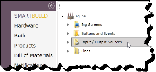
4.Right-click the Input / Output Sources folder and select New, and the select the Source type you want to create. The New Network Serial Input Source dialog opens.
5.Type a name for the new Source and click OK. The new Source is displayed in the Input / Output Sources folder and the Details pane populates with the Source’s attributes.
Figure 22: Network Serial Input Source Details pane
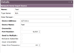
6.Configure the following attributes:
Refer to the table Heading3.
7.When you have completed configuring the attributes, click Save.
Creating a Pick Light Input Source
To create a Pick Light Input Source, follow these steps.
1.If you are not already in the SmartBuild interface, click on the Portal > SmartBuild button. The SmartBuild interface opens.
2.On the SmartBuild panel, select Hardware. The Hardware workspace opens and displays your facilities.
3.Expand the facility you want to work with, and continue to expand through Lines and Stations as necessary to view the Input / Output Sources folder you want to work with.
Figure 23: Line Input / Output Sources folder

4.Right-click the Input / Output Sources folder and select New, and the select the Source type you want to create. The New Pick Light Input Source dialog opens.
5.Type a name for the new Source and click OK. The new Source is displayed in the Input / Output Sources folder and the Details pane populates with the Source’s attributes.
Figure 24: Pick Light Input Source Details pane
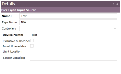
6.Configure the following attributes:
Refer to the table Heading3.
7.When you have completed configuring the attributes, click Save.
Creating a Serial Barcode Scanner Input Source
To create a Serial Barcode Scanner Input Source, follow these steps.
1.If you are not already in the SmartBuild interface, click on the Portal > SmartBuild button. The SmartBuild interface opens.
2.On the SmartBuild panel, select Hardware. The Hardware workspace opens and displays your facilities.
3.Expand the facility you want to work with, and continue to expand through Lines and Stations as necessary to view the Input / Output Sources folder you want to work with.
Figure 25: Line Input / Output Sources folder

4.Right-click the Input / Output Sources folder and select New, and the select the Source type you want to create. The New Serial Barcode Scanner Input Source dialog opens.
5.Type a name for the new Source and click OK. The new Source is displayed in the Input / Output Sources folder and the Details pane populates with the Source’s attributes.
Figure 26: Serial Barcode Scanner Input Source Details pane
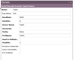
6.Configure the following attributes:
Refer to the table Heading3.
7.When you have completed configuring the attributes, click Save.
Creating a List Select Input Source
To create a List Select Input Source, follow these steps.
1.If you are not already in the SmartBuild interface, click on the Portal > SmartBuild button. The SmartBuild interface opens.
2.On the SmartBuild panel, select Hardware. The Hardware workspace opens and displays your facilities.
3.Expand the facility you want to work with, and continue to expand through Lines and Stations as necessary to view the Input / Output Sources folder you want to work with.
Figure 27: Line Input / Output Sources folder

4.Right-click the Input / Output Sources folder and select New, and the select the Source type you want to create. The New List Select Input Source dialog opens.
5.Type a name for the new Source and click OK. The new Source is displayed in the Input / Output Sources folder and the Details pane populates with the Source’s attributes.
Figure 28: List Select Input Source Details pane
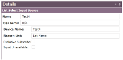
6.Configure the following attributes:
Refer to the table Heading3.
7.When you have completed configuring the attributes, click Save.
Creating an OPC Generic Tag Item Input Source
To create an OPC Generic Tag Item Input Source, follow these steps.
1.If you are not already in the SmartBuild interface, click on the Portal > SmartBuild button. The SmartBuild interface opens.
2.On the SmartBuild panel, select Hardware. The Hardware workspace opens and displays your facilities.
3.Expand the facility you want to work with, and continue to expand through Lines and Stations as necessary to view the Input / Output Sources folder you want to work with.
Figure 29: Line Input / Output Sources folder

4.Right-click the Input / Output Sources folder and select New, and the select the Source type you want to create. The New OPC Generic Tag Item Input Source dialog opens.
5.Type a name for the new Source and click OK. The new Source is displayed in the Input / Output Sources folder and the Details pane populates with the Source’s attributes.
Figure 30: OPC Generic Tag Item Input Source Details pane
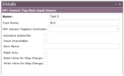
6.Configure the following attributes:
Refer to the table Heading3.
7.When you have completed configuring the attributes, click Save.
Creating a Loftware Print Document
To create a Loftware Print Document, follow these steps.
1.If you are not already in the SmartBuild interface, click on the Portal > SmartBuild button. The SmartBuild interface opens.
2.On the SmartBuild panel, select Hardware. The Hardware workspace opens and displays your facilities.
3.Expand the facility you want to work with, and continue to expand through Lines and Stations as necessary to view the Input / Output Sources folder you want to work with.
Figure 31: Line Input / Output Sources folder

4.Right-click the Input / Output Sources folder and select New, and the select the Source type you want to create. The New Loftware Print Document dialog opens.
5.Type a name for the new Source and click OK. The new Source is displayed in the Input / Output Sources folder and the Details pane populates with the Source’s attributes.
Figure 32: Loftware Print Document Details pane
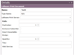
6.Configure the following attributes:
Refer to the table Heading3.
7.When you have completed configuring the attributes, click Save.
Creating Fastening Input Sources
A Fastening Input Source provides information on fastening operations to the PINpoint system.
Creating an Open Protocol Fastening Tool Input Source
To create an Open Protocol Fastening Tool Input Source, follow these steps.
1.If you are not already in the SmartBuild interface, click on the Portal > SmartBuild button. The SmartBuild interface opens.
2.On the SmartBuild panel, select Hardware. The Hardware workspace opens and displays your facilities.
3.Expand the facility you want to work with, and continue to expand through Lines and Stations as necessary to view the Input / Output Sources folder you want to work with.
Figure 33: Line Input / Output Sources folder

4.Right-click the Input / Output Sources folder and select New, and the select the Source type you want to create. The New Open Protocol Fastening Tool Input Source dialog opens.
5.Type a name for the new Source and click OK. The new Source is displayed in the Input / Output Sources folder and the Details pane populates with the Source’s attributes.
Figure 34: Open Protocol Fastening Tool Input Source Details pane
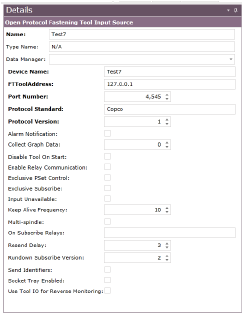
6.Configure the following attributes:
Refer to the table Heading3.
7.When you have completed configuring the attributes, click Save.
Creating a Positional Fastening Tool Input Source
To create a Positional Fastening Tool Input Source, follow these steps.
1.If you are not already in the SmartBuild interface, click on the Portal > SmartBuild button. The SmartBuild interface opens.
2.On the SmartBuild panel, select Hardware. The Hardware workspace opens and displays your facilities.
3.Expand the facility you want to work with, and continue to expand through Lines and Stations as necessary to view the Input / Output Sources folder you want to work with.
Figure 35: Line Input / Output Sources folder

4.Right-click the Input / Output Sources folder and select New, and the select the Source type you want to create. The New Positional Fastening Tool Input Source dialog opens.
5.Type a name for the new Source and click OK. The new Source is displayed in the Input / Output Sources folder and the Details pane populates with the Source’s attributes.
Figure 36: Positional Fastening Tool Input Source Details pane
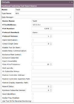
6.Configure the following attributes:
Refer to the table Heading3.
7.When you have completed configuring the attributes, click Save.
Creating a Stanley Wireless Wrench CA Series
To create a Stanley Wireless Wrench CA Series, follow these steps.
1.If you are not already in the SmartBuild interface, click on the Portal > SmartBuild button. The SmartBuild interface opens.
2.On the SmartBuild panel, select Hardware. The Hardware workspace opens and displays your facilities.
3.Expand the facility you want to work with, and continue to expand through Lines and Stations as necessary to view the Input / Output Sources folder you want to work with.
Figure 37: Line Input / Output Sources folder

4.Right-click the Input / Output Sources folder and select New, and the select the Source type you want to create. The New Stanley Wireless Wrench CA Series dialog opens.
5.Type a name for the new Source and click OK. The new Source is displayed in the Input / Output Sources folder and the Details pane populates with the Source’s attributes.
Figure 38: Stanley Wireless Wrench CA Series Details pane
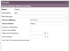
6.Configure the following attributes:
Refer to the table Heading3.
7.When you have completed configuring the attributes, click Save.
Creating a Desoutter CP CVI PC4 Serial
To create a Desoutter CP CVI PC4 Serial, follow these steps.
1.If you are not already in the SmartBuild interface, click on the Portal > SmartBuild button. The SmartBuild interface opens.
2.On the SmartBuild panel, select Hardware. The Hardware workspace opens and displays your facilities.
3.Expand the facility you want to work with, and continue to expand through Lines and Stations as necessary to view the Input / Output Sources folder you want to work with.
Figure 39: Line Input / Output Sources folder

4.Right-click the Input / Output Sources folder and select New, and the select the Source type you want to create. The New Desoutter CP CVI PC4 Serial dialog opens.
5.Type a name for the new Source and click OK. The new Source is displayed in the Input / Output Sources folder and the Details pane populates with the Source’s attributes.
Figure 40: Desoutter CP CVI PC4 Serial Details pane
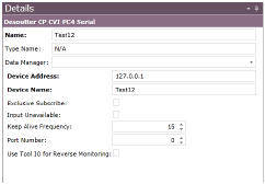
6.Configure the following attributes:
Refer to the table Heading3.
7.When you have completed configuring the attributes, click Save.
Creating an OPC Fastening Tool Input Source
To create an OPC Fastening Tool Input Source, follow these steps.
1.If you are not already in the SmartBuild interface, click on the Portal > SmartBuild button. The SmartBuild interface opens.
2.On the SmartBuild panel, select Hardware. The Hardware workspace opens and displays your facilities.
3.Expand the facility you want to work with, and continue to expand through Lines and Stations as necessary to view the Input / Output Sources folder you want to work with.
Figure 41: Line Input / Output Sources folder

4.Right-click the Input / Output Sources folder and select New, and the select the Source type you want to create. The New OPC Fastening Tool Input Source dialog opens.
5.Type a name for the new Source and click OK. The new Source is displayed in the Input / Output Sources folder and the Details pane populates with the Source’s attributes.
Figure 42: OPC Fastening Tool Input Source Details pane
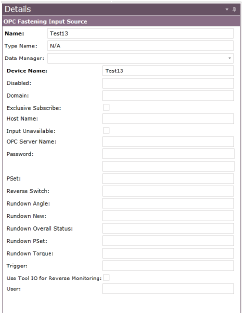
6.Configure the following attributes:
Refer to the table Heading3.
7.When you have completed configuring the attributes, click Save.
Creating an OPC Hybrid Desoutter CP CVI PC4 Serial
To create an OPC Hybrid Desoutter CP CVI PC4 Serial, follow these steps.
1.If you are not already in the SmartBuild interface, click on the Portal > SmartBuild button. The SmartBuild interface opens.
2.On the SmartBuild panel, select Hardware. The Hardware workspace opens and displays your facilities.
3.Expand the facility you want to work with, and continue to expand through Lines and Stations as necessary to view the Input / Output Sources folder you want to work with.
Figure 43: Line Input / Output Sources folder

4.Right-click the Input / Output Sources folder and select New, and the select the Source type you want to create. The New OPC Hybrid Desoutter CP CVI PC4 Serial dialog opens.
5.Type a name for the new Source and click OK. The new Source is displayed in the Input / Output Sources folder and the Details pane populates with the Source’s attributes.
Figure 44: OPC Hybrid Desoutter CP CVI PC4 Serial Details pane
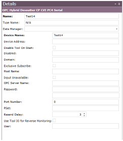
6.Configure the following attributes:
Refer to the table Heading3.
7.When you have completed configuring the attributes, click Save.
Creating an Aimco UEC-4500 Serial
To create an Aimco UEC-4500 Serial, follow these steps.
1.If you are not already in the SmartBuild interface, click on the Portal > SmartBuild button. The SmartBuild interface opens.
2.On the SmartBuild panel, select Hardware. The Hardware workspace opens and displays your facilities.
3.Expand the facility you want to work with, and continue to expand through Lines and Stations as necessary to view the Input / Output Sources folder you want to work with.
Figure 45: Line Input / Output Sources folder

4.Right-click the Input / Output Sources folder and select New, and the select the Source type you want to create. The New Aimco UEC-4500 Serial dialog opens.
5.Type a name for the new Source and click OK. The new Source is displayed in the Input / Output Sources folder and the Details pane populates with the Source’s attributes.
Figure 46: Aimco UEC-4500 Serial Details pane
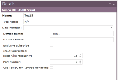
6.Configure the following attributes:
Refer to the table Heading3.
7.When you have completed configuring the attributes, click Save.
Creating an Acradyne IEC Standard Serial
To create an Acradyne IEC Standard Serial, follow these steps.
1.If you are not already in the SmartBuild interface, click on the Portal > SmartBuild button. The SmartBuild interface opens.
2.On the SmartBuild panel, select Hardware. The Hardware workspace opens and displays your facilities.
3.Expand the facility you want to work with, and continue to expand through Lines and Stations as necessary to view the Input / Output Sources folder you want to work with.
Figure 47: Line Input / Output Sources folder

4.Right-click the Input / Output Sources folder and select New, and the select the Source type you want to create. The New Acradyne IEC Standard Serial dialog opens.
5.Type a name for the new Source and click OK. The new Source is displayed in the Input / Output Sources folder and the Details pane populates with the Source’s attributes.
Figure 48: Acradyne IEC Standard Serial Details pane
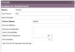
6.Configure the following attributes:
Refer to the table Heading3.
7.When you have completed configuring the attributes, click Save.
Creating a Tester Input Source
A tester is a device which runs a program to test some aspect of a piece of equipment, such as pumping air into a machine to check for a leak, and then reports the results to PINpoint. The results will return an overall status which may have other data within it.
•A tester input source must be linked as a child to a Tester Operation in the SmartBuild > Advanced tab.
•A tester input source must be a child of a data manager.
Creating a Hosted Tester Device
To create a Hosted Tester Device, follow these steps.
1.If you are not already in the SmartBuild interface, click on the Portal > SmartBuild button. The SmartBuild interface opens.
2.On the SmartBuild panel, select Hardware. The Hardware workspace opens and displays your facilities.
3.Expand the facility you want to work with, and continue to expand through Lines and Stations as necessary to view the Input / Output Sources folder you want to work with.
Figure 49: Line Input / Output Sources folder

4.Right-click the Input / Output Sources folder and select New, and the select the Source type you want to create. The New Hosted Tester Device dialog opens.
5.Type a name for the new Source and click OK. The new Source is displayed in the Input / Output Sources folder and the Details pane populates with the Source’s attributes.
Figure 50: Hosted Tester Device Details pane
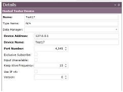
6.Configure the following attributes:
Refer to the table Heading3.
7.When you have completed configuring the attributes, click Save.
Creating an OPC Tester Device
To create an OPC Tester Device, follow these steps.
1.If you are not already in the SmartBuild interface, click on the Portal > SmartBuild button. The SmartBuild interface opens.
2.On the SmartBuild panel, select Hardware. The Hardware workspace opens and displays your facilities.
3.Expand the facility you want to work with, and continue to expand through Lines and Stations as necessary to view the Input / Output Sources folder you want to work with.
Figure 51: Line Input / Output Sources folder

4.Right-click the Input / Output Sources folder and select New, and the select the Source type you want to create. The New OPC Tester Device dialog opens.
5.Type a name for the new Source and click OK. The new Source is displayed in the Input / Output Sources folder and the Details pane populates with the Source’s attributes.
Figure 52: OPC Tester Device Details pane
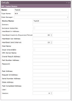
6.Configure the following attributes:
Refer to the table Heading3.
7.When you have completed configuring the attributes, click Save.
Creating a Tester Device
To create a Tester Device, follow these steps.
1.If you are not already in the SmartBuild interface, click on the Portal > SmartBuild button. The SmartBuild interface opens.
2.On the SmartBuild panel, select Hardware. The Hardware workspace opens and displays your facilities.
3.Expand the facility you want to work with, and continue to expand through Lines and Stations as necessary to view the Input / Output Sources folder you want to work with.
Figure 53: Line Input / Output Sources folder

4.Right-click the Input / Output Sources folder and select New, and the select the Source type you want to create. The New Tester Device dialog opens.
5.Type a name for the new Source and click OK. The new Source is displayed in the Input / Output Sources folder and the Details pane populates with the Source’s attributes.
Figure 54: Tester Device Details pane
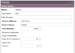
6.Configure the following attributes:
Refer to the table Heading3.
7.When you have completed configuring the attributes, click Save.
Creating a Banner Omni P4 Device
To create a Banner Omni P4 Device, follow these steps.
1.If you are not already in the SmartBuild interface, click on the Portal > SmartBuild button. The SmartBuild interface opens.
2.On the SmartBuild panel, select Hardware. The Hardware workspace opens and displays your facilities.
3.Expand the facility you want to work with, and continue to expand through Lines and Stations as necessary to view the Input / Output Sources folder you want to work with.
Figure 55: Line Input / Output Sources folder

4.Right-click the Input / Output Sources folder and select New, and the select the Source type you want to create. The New Banner Omni P4 Device dialog opens.
5.Type a name for the new Source and click OK. The new Source is displayed in the Input / Output Sources folder and the Details pane populates with the Source’s attributes.
Figure 56: Banner Omni P4 Device Details pane
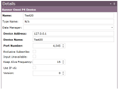
6.Configure the following attributes:
Refer to the table Heading3.
7.When you have completed configuring the attributes, click Save.
Creating a Sentinel C28 Tester Device
To create a Sentinel C28 Tester Device, follow these steps.
1.If you are not already in the SmartBuild interface, click on the Portal > SmartBuild button. The SmartBuild interface opens.
2.On the SmartBuild panel, select Hardware. The Hardware workspace opens and displays your facilities.
3.Expand the facility you want to work with, and continue to expand through Lines and Stations as necessary to view the Input / Output Sources folder you want to work with.
Figure 57: Line Input / Output Sources folder

4.Right-click the Input / Output Sources folder and select New, and the select the Source type you want to create. The New Sentinel C28 Tester Device dialog opens.
5.Type a name for the new Source and click OK. The new Source is displayed in the Input / Output Sources folder and the Details pane populates with the Source’s attributes.
Figure 58: Sentinel C28 Tester Device Details pane
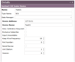
6.Configure the following attributes:
Refer to the table Heading3.
7.When you have completed configuring the attributes, click Save.
Creating a Broadcast Tester Device
To create a Broadcast Tester Device, follow these steps.
1.If you are not already in the SmartBuild interface, click on the Portal > SmartBuild button. The SmartBuild interface opens.
2.On the SmartBuild panel, select Hardware. The Hardware workspace opens and displays your facilities.
3.Expand the facility you want to work with, and continue to expand through Lines and Stations as necessary to view the Input / Output Sources folder you want to work with.
Figure 59: Line Input / Output Sources folder

4.Right-click the Input / Output Sources folder and select New, and the select the Source type you want to create. The New Broadcast Tester Device dialog opens.
5.Type a name for the new Source and click OK. The new Source is displayed in the Input / Output Sources folder and the Details pane populates with the Source’s attributes.
Figure 60: Broadcast Tester Device Details pane
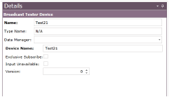
6.Configure the following attributes:
Refer to the table Heading3.
7.When you have completed configuring the attributes, click Save.
Creating a Keyence Device
To create a Keyence Device, follow these steps.
1.If you are not already in the SmartBuild interface, click on the Portal > SmartBuild button. The SmartBuild interface opens.
2.On the SmartBuild panel, select Hardware. The Hardware workspace opens and displays your facilities.
3.Expand the facility you want to work with, and continue to expand through Lines and Stations as necessary to view the Input / Output Sources folder you want to work with.
Figure 61: Line Input / Output Sources folder

4.Right-click the Input / Output Sources folder and select New, and the select the Source type you want to create. The New Keyence Device dialog opens.
5.Type a name for the new Source and click OK. The new Source is displayed in the Input / Output Sources folder and the Details pane populates with the Source’s attributes.
Figure 62: Keyence Device Details pane
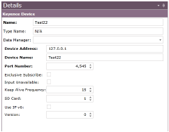
6.Configure the following attributes:
Refer to the table Heading3.
7.When you have completed configuring the attributes, click Save.
Creating a Cognex Device
To create a Cognex Device, follow these steps.
1.If you are not already in the SmartBuild interface, click on the Portal > SmartBuild button. The SmartBuild interface opens.
2.On the SmartBuild panel, select Hardware. The Hardware workspace opens and displays your facilities.
3.Expand the facility you want to work with, and continue to expand through Lines and Stations as necessary to view the Input / Output Sources folder you want to work with.
Figure 63: Line Input / Output Sources folder

4.Right-click the Input / Output Sources folder and select New, and the select the Source type you want to create. The New Cognex Device dialog opens.
5.Type a name for the new Source and click OK. The new Source is displayed in the Input / Output Sources folder and the Details pane populates with the Source’s attributes.
Figure 64: Cognex Device Details pane
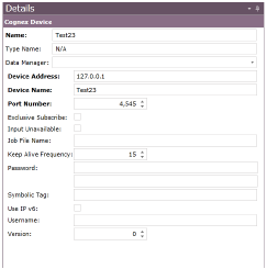
6.Configure the following attributes:
Refer to the table Heading3.
7.When you have completed configuring the attributes, click Save.
A BigScreen is an object in the PINpoint system that enables you to control an actual BigScreen in the facility, and determine what is displayed there. A BigScreen is a computer display that typically provides information concerning the status of stations and problems on the line, as well as metrics concerning production. Gauges, Reports, and Stations can be added to a BigScreen in the Hardware page, but the Buttons and Events associated with them are added in the Notifications page. See Heading3 for instructions.
Creating a BigScreen
To create and configure a BigScreen, follow these steps.
NoteFor the purposes of illustration, the associated screen captures detail the process at the station level, though the instructions are intended to be universally applicable.
1.If you are not already in the SmartBuild interface, click on the Portal > SmartBuild button. The SmartBuild interface opens.
2.On the SmartBuild panel, select Hardware. The Hardware workspace opens and displays your facilities.
3.Expand the facility you want to work with. The BigScreens folder is displayed.
4.Click the BigScreens folder to make it active.
5.Right-click the BigScreens folder and select New > BigScreen Device. The New BigScreen Device dialog opens.
Figure 65: Add new BigScreen
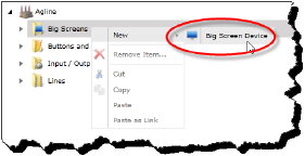
6.Type a name for the new BigScreen and click OK. The new BigScreen is displayed in the BigScreens folder and the Details pane populates with the BigScreen’s attributes.
Figure 66: BigScreen Details pane
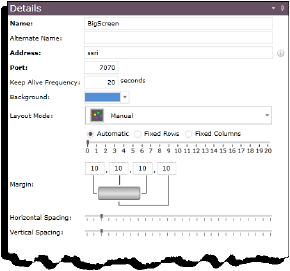
7.Configure the following attributes:
Table 4: BigScreen attributes
|
Attribute |
Description |
|---|---|
|
Name |
This is the provided at the time the BigScreen Device was created. It is possible (though not necessary) to change it using this field. Changing the name here is automatically reflected in the BigScreen Device in the BigScreen’s folder. |
|
Alternate Name |
You may choose to enter an alternative name for the BigScreen Device; e.g., if a different name is required for the purposes of reporting. |
|
Address |
Enter the IP address where the device is located in the network. |
|
Port |
Enter the port number of the BigScreen’s device address. Note that the port number, in combination with the device address, must be unique to the device. If it is not, an error message will display when you attempt to save the BigScreen Device configuration. |
|
Keep Alive Frequency |
This is the frequency in seconds that a keep alive message will be sent to the device. You can type a number directly into this field or use the arrow buttons to raise and lower the value by increments of 1. |
|
Background |
Use this drop-down list to select a standard color for the background of the BigScreen. |
|
Layout Mode |
There are two controls here: •The first is a drop-down menu that enables you to designate the flow order of the stations, with the choices being: •Across Then Down •Down Then Across •Manual •The second control enables you to control the spacing of the station flow. Radio buttons enable you to select whether you want to control the spacing by Fixed Rows or Fixed Columns, or Automatic, which allows the system itself to dynamically arrange the array. In the case of Fixed Rows or Fixed Columns, the slider beneath the radio buttons enables you to set the number of fixed rows, or columns, respectively. |
|
Margin |
These are four value fields where you can enter the number of pixels forming the margins at all four edges of the BigScreen. The default value in each case is 10. |
|
Horizontal Spacing |
Use this sliding scale to designate the horizontal space between stations on the BigScreen. |
|
Vertical Spacing |
Use this sliding scale to designate the vertical space between stations on the BigScreen. |
8.When you have completed configuring the BigScreen Device, click Save.
Previewing a BigScreen
It’s possible to preview the way the configuration of a BigScreen will actually appear when implemented on the line, and to make adjustments more knowledgeably. To do this, follow these steps.
1.If you are not already in the SmartBuild interface, click on the Portal > SmartBuild button. The SmartBuild interface opens.
2.On the SmartBuild panel, select Hardware. The Hardware workspace opens and displays your facilities.
3.Expand the facility you want to work with. The BigScreen’s folder is displayed.
4.Click the BigScreen’s folder to make it active.
5.Select the BigScreen you want to work with.
6.Click the BigScreen Preview button. A view of the BigScreen as configured is displayed at the bottom on the interface.
Figure 67: BigScreen Preview button
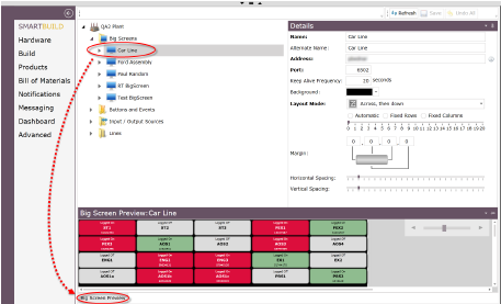
Changes made in the Details pane are reflected by viewing the preview again, and do not require being saved to be viewed. However, changes must be saved in order for them to be put into effect on the actual BigScreen.
The size of the preview is controlled by means of the sliding scale control at the upper right of the preview.
Refreshing a BigScreen
From time to time, you may find reason to refresh the connection between a BigScreen and its Data Manager. To do so, follow these steps.
1.If you are not already in the SmartBuild interface, click on the Portal > SmartBuild button. The SmartBuild interface opens.
2.On the SmartBuild panel, select Hardware. The Hardware workspace opens and displays your facilities.
3.Expand the facility you want to work with, and continue to expand its BigScreens folder to view the BigScreen you want to refresh.
Figure 68: BigScreen folder
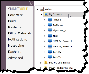
4.Right-click the BigScreen and select Refresh Data Manager for BigScreen. The BigScreen Refresh dialog opens.
Figure 69: BigScreen Refresh dialog
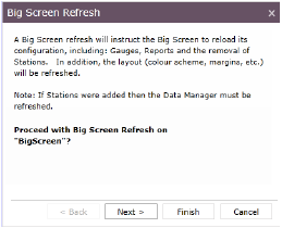
5.Click Next. A dialog opens to inform you of the status of the refresh attempt.
6.Click Close to close the dialog.
Adding a Gauge to a BigScreen
Gauges are used to display various metrics in real time on a BigScreen. There are four types of Gauges that can be added to a BigScreen:
Table 5: Descriptions of Gauge types
|
Type |
Description |
|---|---|
|
Radial |
A Radial Gauge appears on the BigScreen as a circle with a numeric range arrayed at the outer edge and a needle at the center pointing to the current value to which the Gauge is configured. It resembles a speedometer. |
|
Quadrant |
A Quardrant Gauge appears on the BigScreen as a quarter of a circle with values arrayed at the curve and a needle centered at corner, pointing to the current value to which the Gauge is configured. |
|
Linear |
A Linear Gauge appears on the BigScreen as a number line of values with a floating indicator stationed at the current value to which the Gauge is configured. |
|
Numerical |
A Numerical Gauge appears on the BigScreen as an LED displaying an actual numeric value. |
To add a Gauge to a BigScreen, follow these steps.
NoteThese steps are identical for all Gauge types, including the attribute set.
1.If you are not already in the SmartBuild interface, click on the Portal > SmartBuild button. The SmartBuild interface opens.
2.On the SmartBuild panel, select Hardware. The Hardware workspace opens and displays your facilities.
3.Expand the facility you want to work with, and continue to expand its BigScreen’s folder to view the BigScreen you want to work with.
4.Expand the BigScreen you want to work with to view its Gauges folder.
Figure 70: BigScreen Gauges folder
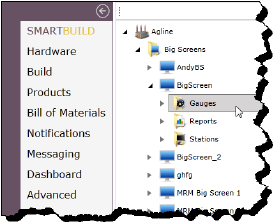
5.Right-click the Gauges folder and select New, and the select the Gauge type you want to create. The New [Gauge Type] Event dialog opens.
6.Type a name for the new Gauge and click OK. The new Gauge is displayed in the Gauges folder and the Details pane populates with the Gauge’s attributes.
Figure 71: Example of a Gauge Details pane
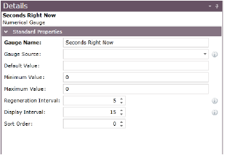
7.Configure the following attributes:
Table 6: Gauge attributes
|
Attribute |
Description |
Data Type |
Input Type |
|---|---|---|---|
|
Gauge Name |
The title on top of the gauge and the name of the Gauge as it appears in SmartBuild. |
Text |
Text Box |
|
Gauge Source |
The type of information from the SQL file. |
Text |
Text Box |
|
Default Value |
The default value is the value the gauge will display unless it receives information from the SQL query. |
Text |
Text Box |
|
Minimum Value |
The minimum value of the Gauge. |
Number |
Counter Box |
|
Maximum Value |
The maximum value of the Gauge. |
Number |
Counter Box |
|
Regeneration Interval |
The length of time in minutes until the data is refreshed. |
Number |
Counter Box |
|
Display Interval |
The length of time in seconds the Gauge will be displayed for. |
Number |
Counter Box |
|
Sort Order |
The order of which Gauge will be displayed in SmartBuild. The order in SmartBuild is the same as the order on the BigScreen. |
Number |
Counter Box |
8.When you have completed configuring the Gauge’s attributes, click Save.
Adding a Report to a BigScreen
Reports are used on a BigScreen to display information about Station status over a determined period.
1.If you are not already in the SmartBuild interface, click on the Portal > SmartBuild button. The SmartBuild interface opens.
2.On the SmartBuild panel, select Hardware. The Hardware workspace opens and displays your facilities.
3.Expand the facility you want to work with, and continue to expand its BigScreen’s folder to view the BigScreen you want to work with.
4.Expand the BigScreen you want to work with to view its Reports folder.
Figure 72: BigScreen Reports folder
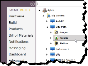
5.Right-click the Reports folder and select New, and the select Report. The New Report dialog opens.
6.Type a name for the new Report and click OK. The new Report is displayed in the Reports folder and the Details pane populates with the Report’s attributes.
Figure 73: Reports Details pane
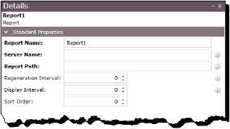
7.Configure the following attributes:
Table 7: Report attributes
|
Attribute |
Description |
Data Type |
Input Type |
|---|---|---|---|
|
Report Name |
The name of the Report as seen in SmartBuild. |
Text |
Text Box |
|
Server Name |
The name of the server where the report server exists. |
Text |
Text Box |
|
Report Path |
The path of the report on the report server. |
Text |
Text Box |
|
Regeneration Interval |
The length of time in minutes until the data is refreshed. |
Number |
Counter Box |
|
Display Interval |
The length of time in seconds the Report will be displayed for. |
Number |
Counter Box |
|
Sort Order |
The order of which Report will be displayed in SmartBuild. The order in SmartBuild is the same as the order on the BigScreen. |
Number |
Counter Box |
8.When you have completed configuring the Report’s attributes, click Save.
Adding a Station to a BigScreen
In order for Stations to be associated with, and appear on, a BigScreen, you must add them to the BigScreen. To add a Station to a BigScreen, follow these steps.
1.If you are not already in the SmartBuild interface, click on the Portal > SmartBuild button. The SmartBuild interface opens.
2.On the SmartBuild panel, select Hardware. The Hardware workspace opens and displays your facilities.
3.Expand the facility you want to work with, and continue to expand its BigScreen’s folder to view the BigScreen you want to work with.
Figure 74: Expanding the BigScreen’s folder
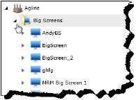
4.Expand the Line in question and its Stations folder to access the Station you want to add to the BigScreen.
Figure 75: Viewing the Stations of a Line
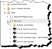
5.Click-drag the Station and drop it on the BigScreen to which you want to add it. The Station is displayed in the BigScreen’s Stations folder.
Figure 76: Dragging a Station to a BigScreen
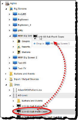
6.Click Save to commit your changes.
PINpoint includes an extensive range of production line events that either affect production or are typically brought to the attention of people managing it. Events (as well as the Buttons that can be associated with them) are created and modified point using the Hardware page in SmartBuild, and grouped in various Buttons and Events folders.
WarningIt is vitally important to understand that Buttons are not intended to, and do not, offer the functionality of emergency stop buttons or devices. They are intended solely for the purpose of communicating events, issues, and statuses to signaling devices and PINpoint for the purposes of tracking and reporting only.
Figure 77: Event Types
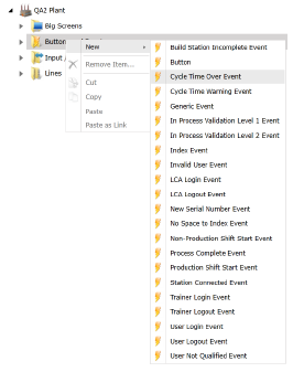
Table 8: Descriptions of Event types
|
Event |
Description |
Source of Event |
Default states |
|---|---|---|---|
|
Build Station Incomplete Event |
This event is true when the station is active but not complete. |
This event is generated by the Client during the product identification stage in the case where the process for the product being identified has not been successfully completed at previous stations. |
•'Momentary event' = True |
|
Button |
The user can create on screen buttons within SmartBuild which show up on the SmartScreen Client. The buttons show up on all screens after the login. A button is an event written in the Hardware page and can be used in the Notifications page. A button can also trigger an event using the Associated event dropdown. Buttons can be hidden and their access limited to different user levels. |
This event is generated by the Client when a defined button is pressed. |
Possible states: •0,2,1 (off/flashing/on) |
|
Cycle Time Over Event |
The Cycle Time Over Event is true when the cycle time is beyond the "CycleTime Over Percent", as defined in the Extended Properties of the Station configuration in the Hardware page. |
This event is generated by the Client when the cycle time for a specific product at a specific station has been exceeded. |
•'Color' = Black •'Momentary event' = False •'Is Interlockable' = False •'Statuses' = 0,1 |
|
Cycle Time Warning Event |
The Cycle Time Warning Event is true when the cycle time is beyond the "CycleTime Warning Percent", as defined in the Extended Properties of the Station configuration in the Hardware page. |
This event is generated by the Client when the cycle time warning trigger threshold for a specific product at a specific station has been exceeded. |
•'Color' = Black •'Momentary event' = False •'Statuses' = 0,1 |
|
Generic Event |
This is an event triggered using the PLC. |
This event is generated by an external source (typically an OPC connection). |
•'Color' = Black •'Momentary event' = False •'Is Interlockable' = False •'Statuses' = 0,2,1 |
|
In Process Validation Level 1 Event |
This happens when an operator makes a bad/NOK rundown. The tool locks requires the operator to clear the tool lock. |
This event is generated by the Client when an InProcess Validation Level 1 is activated. |
•'Color' = Black •'Momentary event' = False •'Statuses' = 0,1 |
|
In Process Validation Level 2 Event |
This happens when an operator makes a certain number of consecutive wrong rundowns, with that number set in configuration. The tool locks and an LCA to clear the lock. |
This event is generated by the Client when an InProcess Validation Level 2 is activated. |
•'Color' = Black •'Momentary event' = False •'Statuses' = 0,2,1 |
|
Index Event |
This is triggered internally by PINpoint. |
Whenever a sync cluster is indexed, either by the last station complete in the cluster, or the tracking site, the index event will trigger. |
•'Momentary event' = True |
|
Invalid User Event |
This event is true when an invalid user attempts to log in. |
This event is generated by the Client when a level 0 operator attempts to log into a client.
The invalid user event is only published under certain conditions: •NotAllowedAtStation (Level 0) •OperatorIsNotATrainer •MasterBuildRequired •OperatorCapacityMetOrExceeded |
•'Momentary event' = True |
|
LCA Login Event |
This event is true when an LCA logs in to the station. |
This event is generated by the Client when an LCA user logs into a client. |
•'Momentary event' = True |
|
LCA Logout Event |
This event is true when an LCA logs out of a station. |
This event is generated by the Client when an LCA user logs off a client. |
•'Momentary event' = True |
|
New Serial Number |
This event is true when a station loads a new serial number. |
This event is generated by the Client when a new serial number is started on the Client. |
•'Momentary event' = True |
|
No Space to Index Event |
This event is true when the outbound Queue of a set of Stations using Auto Indexing currently holds its Destination Capacity (maximum number) of Products. |
This event is generated by the Tracking Manager having the requisite signals to Auto Index a set of Stations when the Destination Capacity (maximum number) of Products is currently present in the outbound Queue. |
•'Momentary event' = False •'Statuses' = 0,1 |
|
Non-Production Shift Start Event |
This event is true when the shift schedule enters non-production time. |
This event is generated by the Andon Data Manager. |
•'Momentary event' = True |
|
Process Complete Event |
This event is true when a step is completed. |
This event is generated by the Client whenever there is a change in the number of completed process steps. |
•'Momentary event' = True |
|
Production Shift Start Event |
This event is true when the shift schedule enters production time. |
This event is generated by the Andon Data Manager. |
•'Momentary event' = True |
|
Station Connected Event |
This is an event that is fired when a station loses its connection to the server. The BigScreen will also display a disconnected icon. |
This event is generated by the ANDON data manager to indicate an individual stations connection status on the BigScreen. |
•'Color' = Black •'Momentary event' = False •'Statuses' = 0,1 |
|
Trainer Login Event |
This event occurs when a user with a level 3 trainer status logs into a station. |
This event is generated by the Client when a trainer logs into a client. |
•'Momentary event' = True |
|
Trainer Logout Event |
This event is true when a user with a level 3 trainer status logs out of a station. |
This event is generated by the Client when a trainer logs off a client. |
•'Momentary event' = True |
|
User Login Event |
This event is true when a user logs in to a station. |
This event is generated by the Client when a user logs into a client. |
•This event is generated by the Client when a user logs into a client. |
|
User Logout Event |
This event is true when a user logs out of a station. |
This event is generated by the Client when a user logs off a client. |
•'Momentary event' = True |
|
User Not Qualified Event |
This event is true when a user logs into a station which the user is not qualified to operate. |
This event is generated by the Client when an unqualified user logs into a client. |
•This event is generated by the Client when an unqualified user logs into a client. |
Table 9: Event priorities when linked to the same BSSO
|
PriorityA |
Event Name |
|---|---|
|
1 |
InProcess Validation Level 3 |
|
2 |
Cycle Time Over Event |
|
3 |
InProcess Validation Level 2 |
|
4 |
Button Event - all buttons treated equally |
|
5 |
Generic Event |
|
6 |
Cycle Time Warning Event |
|
7 |
Cycle Time Warning Event |
|
AThis is the priority the events are to be processed/displayed when linked to the same BSSO and has nothing to do with the 'Priority' attribute in SmartBuild > Hardware at the event definition level. |
To create and configure an Event, follow these steps.
NoteFor the purposes of illustration, the associated screen captures detail the process at the station level, though the instructions are intended to be universally applicable.
1.If you are not already in the SmartBuild interface, click on the Portal > SmartBuild button. The SmartBuild interface opens.
2.On the SmartBuild panel, select Hardware. The Hardware workspace opens and displays your facilities.
3.Expand the facility you want to work with, and continue to expand through Lines and Stations as necessary to view the Buttons and Events folder you want to work with.
Figure 78: Station Buttons and Events folder
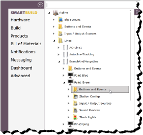
4.Select the Buttons and Events folder and right-click it. Select New, and the select the Event type you want to create. The New [Event Type] Event dialog opens.
5.Type a name for the new Event and click OK. The new Event is displayed in the Buttons and Events folder and the Details pane populates with the Event’s attributes.
Figure 79: Example of an Event Details Pane
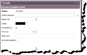
6.Configure the following attributes:
Refer to the table Heading3.
7.When you have completed configuring the Event’s attributes, click Save.
Creating a Button
Buttons appear on the SmartScreen Client used at stations on the production line, and can be assigned to trigger different events, emails and text messages, activate Andon equipment, and so on.
WarningIt is vitally important to understand that Buttons are not intended to, and do not, offer the functionality of emergency stop buttons or devices. They are intended solely for the purpose of communicating events, issues, and statuses to signaling devices and PINpoint for the purposes of tracking and reporting only.
To create a button, follow these steps.
NoteFor the purposes of illustration, the associated screen captures detail the process at the station level, though the instructions are intended to be universally applicable.
1.If you are not already in the SmartBuild interface, click on the Portal > SmartBuild button. The SmartBuild interface opens.
2.On the SmartBuild panel, select Hardware. The Hardware workspace opens and displays your facilities.
3.Expand the facility you want to work with, and continue to expand through Lines and Stations as necessary to view the Buttons and Events folder you want to work with.
Figure 80: Station Buttons and Events folder

4.Select the Buttons and Events folder and right-click it. Select New > Button. The New Button dialog opens.
5.Type a name for the new Button and click OK. The new Button is displayed in the Buttons and Events folder and the Details pane populates with the Button’s attributes.
Figure 81: Example of a Button Details Pane
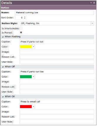
6.Configure the following attributes:
Refer to the table Heading3.
7.When you have completed configuring the Button’s attributes, click Save.