Portal > SmartBuild > Advanced
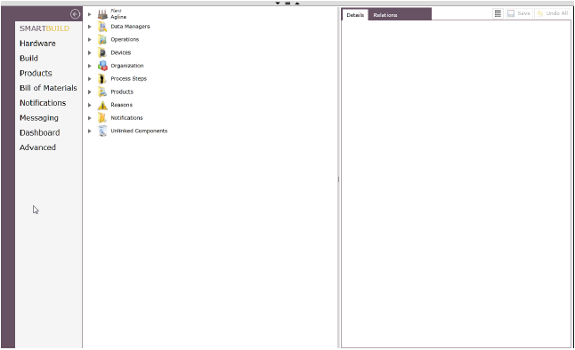
The Advanced tab serves as a single location where all the components created in SmartBuild are gathered and categorized to be easily located, viewed, and in some instances created as well. Components can have their editable parameters viewed and changed in the Details pane. The relationships between a component and other components in PINpoint can be viewed and easily understood using the Relations pane.
Figure 210: Advanced tab

Advanced Page Panes
The tab is divided into three panes: Components, Details, and Relations.
Components Pane
The Components pane displays the components categories and arranges components in logical hierarchies based on their dependencies (for example, a Station Configuration is nested under its Station, which is itself nested under its Line, with Lines nested under the Plant).
While most components are typically created and configured in other tabs of SmartBuild, a wide variety of components can not only be viewed and edited in the Advanced tab, but created in it as well. In a few cases, the Advanced tab is the only place certain components can be created.
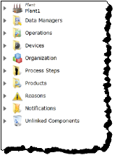
Components are organized into the following categories:
•Plant: principally organizes the Lines, Stations, BigScreens, and general Events, though can also contain other components.
•Data Managers: organizes the Data Managers in the system. This is the place in which Data Managers are created in PINpoint Portal.
•Operations: organizes Operations available for use by Process Steps.
•Devices: organizes devices available to Stations and BigScreens for the input and output of data, and controllers to manage those devices.
•Organization: organizes Global Settings for PINpoint, external email-to-text providers, and the Custom Contextual Data used by PINpoint Tracking. This is the place in which Custom Contextual Data is created in PINpoint Portal.
•Process Steps: organizes all the Process Steps created in PINpoint.
•Products: organizes all the Products built in PINpoint, the Process Steps involved in building them, and the Stations at which they are built.
•Reasons: organizes the Reasons used in the system to apply to problems in production and to organize Andon reports into time loss buckets. This is the place in which Reasons are created in PINpoint Portal.
•Notifications: organizes the Notifications used in the system to alert designated people via Stations, BigScreens, text, email, and other devices of certain Events in production.
•Unlinked Components: organizes components which have been created in PINpoint but are not currently linked to other components in a process.
Figure 211: Components pane
Details Pane
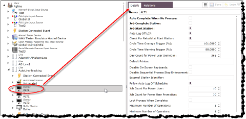
The Details pane provides information on the settings of the parameters of the currently-selected component. In addition, it enables you to make changes to those parameters and save those changes.
Figure 212: Details pane
Relations Pane
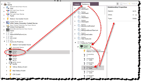
The Relations pane shows the relationships between the currently-selected component and other components which have either a parent or child relationship to it in the PINpoint system. This is particularly useful for components that can be reused and have numerous independent relationships with other components.
Figure 213: Relations pane
Advanced Page Definitions
The following definitions summarize concepts you will encounter in this section.
Table 34: Advanced page definitions
|
Term |
Definition |
|---|---|
|
Data Manager |
The Data Manager is a Windows service that manages communication between the physical world and client applications. The Data Manager has three main modules: •Device Manager: provides a communication layer between TCP/IP, and OPC devices using Device specific drivers (e.g., Open Protocol Tools, PLCs, Stack Lights, Tester Devices, PINpoint BigScreens, etc.). •Event Manager: routes inbound events from client applications to various subsystems both internal and external. •Tracking Manager: informs the Client Application what product to build, and informs subsystems with updates from the Client concerning the progress of the product assembly. |
Copying and Pasting
One of the most useful functions of the Advanced tab is the ability to copy a component and all of its subcomponents and paste a copy of them, or a link to them, into the hierarchy of another appropriate component. For example, a Station and all of its Andon collateral and Process Steps can be copied and pasted as a copy in all respects into another Line, saving the trouble of setting up an essentially identical Station every time (note that the exception is that Input Sources attached to Fastening Steps are not copied, in order to prevent the user from accidentally linking an Input Source to a wrong station.
Figure 214: Copy and Paste in Advanced tab

Using the Paste as Link option links the object to another component. In this case, no actual copied components are created.
Removing Components
Most components can be removed from a hierarchy in which they currently reside. If all the relationships a component has are removed, that component will be located in the Unlinked Components folder (see Heading3).
To remove a component from a hierarchy, follow these steps.
1.Right-click the component and select Remove Item....
Figure 215: Select Remove Items...
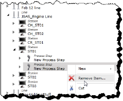
The Remove Items dialog opens. The relationship is selected by default, but all the other relationships of the item are also available for selection, if desired.
Figure 216: Remove Items dialog with relationship pre-selected
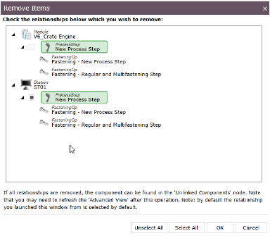
2.Ensure that all the relationships you want to remove the component from are selected and click OK. The component is removed from the indicated relationship(s). If all relationships were selected, the component can be found in the Unlinked Components folder.
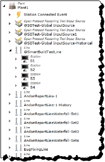
Plant Folder
The Plant hierarchy principally organizes the Lines, Stations, BigScreens, and general Events, though can also contain other components.
In addition, right-clicking the Plant icon provides the user with the ability to directly create and configure a wide variety of components.
Figure 217: Plant hierarchy
Creating New Components at the Plant Level
To create a new component using the Plant folder itself, follow these steps.
1.If you are not already in the SmartBuild interface, click on the Portal > SmartBuild button. The SmartBuild interface opens.
2.On the SmartBuild panel, select Advanced. The Advanced workspace opens.
3.Right-click the Plant icon and hover the mouse pointer over New to view the options. Select the component you want to create (use Figure 218: Plant menu New component type options as a navigation aid).
Figure 218: Plant menu New component type options
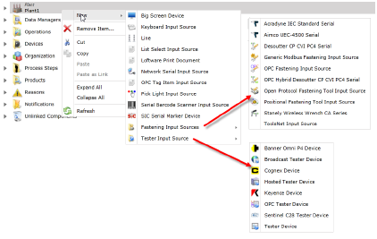
The dialog for naming the component type you selected opens.
4.Type a name for the new component.
5.Click Next. The dialog for configuring the attributes of your new component opens.
You can use the following table to reference the list of your component’s attributes and descriptions of their purposes, if required.
Table 35: Component attribute lookup links
6.When you have completed configuring the attributes, click Finish. The new component is displayed in the Plant folder.
Creating New Sub-components in Lines
To create a new component for a Line, follow these steps.
1.If you are not already in the SmartBuild interface, click on the Portal > SmartBuild button. The SmartBuild interface opens.
2.On the SmartBuild panel, select Advanced. The Advanced workspace opens.
3.Expand the Plant hierarchy and locate the Line you want to work with.
4.Right-click the Line icon and hover the mouse pointer over New to view the options. Select the component you want to create.
Figure 219: Line menu New component type options
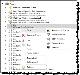
The dialog for naming the component type you selected opens.
5.Type a name for the new component.
6.Click Next. The dialog for configuring the attributes of your new component opens.
You can use the following table to reference the list of your component’s attributes and descriptions of their purposes, if required.
Table 36: Component attribute lookup links
7.When you have completed configuring the attributes, click Finish. The new component is displayed in the Line folder.
Creating New Sub-components for Stations
To create a new component for a Station, follow these steps.
1.If you are not already in the SmartBuild interface, click on the Portal > SmartBuild button. The SmartBuild interface opens.
2.On the SmartBuild panel, select Advanced. The Advanced workspace opens.
3.Expand the Plant hierarchy and locate the Line you want to work with.
4.Expand the Line hierarchy and locate the Station you want to work with.
5.Right-click the Station icon and hover the mouse pointer over New to view the options. Select the component you want to create.
Figure 220: Station menu New component type options

The dialog for naming the component type you selected opens.
6.Type a name for the new component.
7.Click Next. The dialog for configuring the attributes of your new component opens.
You can use the following table to reference the list of your component’s attributes and descriptions of their purposes, if required.
Table 37: Component attribute lookup links
|
|
8.When you have completed configuring the attributes, click Finish. The new component is displayed in the Station folder.
Creating New Sub-components for BigScreens
To create a new component for a BigScreen, follow these steps.
1.If you are not already in the SmartBuild interface, click on the Portal > SmartBuild button. The SmartBuild interface opens.
2.On the SmartBuild panel, select Advanced. The Advanced workspace opens.
3.Expand the Plant hierarchy and locate the BigScreen you want to work with.
4.Right-click the BigScreen icon and hover the mouse pointer over New to view the options. Select the component you want to create.
Figure 221: BigScreen menu New component type options

The dialog for naming the component type you selected opens.
5.Type a name for the new component.
6.Click Next. The dialog for configuring the attributes of your new component opens.
You can use the following table to reference the list of your component’s attributes and descriptions of their purposes, if required.
Table 38: Component attribute lookup links
7.When you have completed configuring the attributes, click Finish. The new component is displayed in the BigScreen folder.
Editing Existing Components
To edit existing components organized in the Plant hierarchy, follow these steps.
1.If you are not already in the SmartBuild interface, click on the Portal > SmartBuild button. The SmartBuild interface opens.
2.On the SmartBuild panel, select Advanced. The Advanced workspace opens.
3.Expand the Plant hierarchy, and those of any subcomponents necessary, and locate the component whose attributes you want to edit.
4.Select the component. Its attributes populate the Details pane.
5.Make the changes you require to the component’s attributes.
You can use the following table to reference the list of your component’s attributes and descriptions of their purposes, if required.
Table 39: Component attribute lookup links
6.When you have completed configuring the attributes, click Save. The component’s updated attributes are applied.
Data Managers Folder
The Data Managers folder organizes the Data Managers created in your instance of PINpoint, and enables you to create new ones and modify the attributes of existing ones.
The Data Manager is a Windows service that manages communication between the physical world and client applications. The Data Manager has three main modules:
•Device Manager: provides a communication layer between TCP/IP, and OPC devices using Device specific drivers (e.g., Open Protocol Tools, PLCs, Stack Lights, Tester Devices, PINpoint BigScreens, etc.).
•Event Manager: routes inbound events from client applications to various subsystems both internal and external.
•Tracking Manager: informs the Client Application what product to build, and informs subsystems with updates from the Client concerning the progress of the product assembly. The Tracking Manager is designated by supplying the value 32000 to the attribute Tracking Client Connection Port in the manager’s Details.
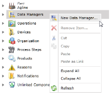
Figure 222: Data Managers menu
Creating New Data Managers
To create a new Data Manager, follow these steps.
1.If you are not already in the SmartBuild interface, click on the Portal > SmartBuild button. The SmartBuild interface opens.
2.On the SmartBuild panel, select Advanced. The Advanced workspace opens.
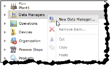
3.Right-click the Data Managers icon and select New Data Manager....
Figure 223: Select New Data Manager
The dialog for naming the new Data Manager opens.
4.Type a name for the new Data Manager.
5.Click Next. The dialog for configuring the attributes of your new Data Manager opens.
6.Configure the following attributes:
Table 40: Component attribute lookup links
|
Attribute |
Description |
Date Type |
Input Type |
|---|---|---|---|
|
Client Connect PortA |
The port used by the client computer to communicate with the server. |
Number |
Counter Box |
|
Instance IDa |
The instance number of the data manager running on the server, usually 4040. If setting up a different data manager on the same server you must change the instance ID and the client connection port, and event client connection port. |
Number |
Counter Box |
|
Server Namea |
The IP address of the server |
Text |
Text Box |
|
Service Instance Namea |
The name of the service running on a server. |
Text |
Text Box |
|
Client Inactivity Disconnect Period |
The number of seconds of inactivity before the data manager will disconnect the client. |
Number |
Counter Box |
|
Event Client Connection Port |
The port used by the server to communicate with the client computer. |
Number |
Counter Box |
|
Host Address |
The IP Address that the Data Manager listens on; for multi-homed servers it is the default NIC if none is specified. |
Text |
Text Box |
|
SortOrder |
The order of item in PINpoint. If this value is changed, the user must refresh SmartBuild before changes are reflected. |
Number |
Counter Box |
|
Station Connection Timeout Tolerance |
The number of seconds the DataManager will wait before assuming there is a Station Connection issue. |
Number |
Counter Box |
|
Station Connection Verification Interval |
The frequency in seconds at which Station connections are verified, 60 seconds in the minimum. |
Number |
Counter Box |
|
Station Connection Verification Startup Delay |
The number of seconds to delay verification of Station Connections after the DataManager starts. |
Number |
Counter Box |
|
Tracking |
|||
|
Broadcast Web Address |
The address of the Web Service to be called tor broadcast Build Item changes. |
Text |
Text Box |
|
Broadcast Web Method |
The Web Method to be called tor broadcast Build Item changes. |
Text |
Text Box |
|
Domain |
The domain the tool is connected to. |
Text |
Text Box |
|
Heartbeat In Address |
Address for Heartbeat In. |
Text |
Text Box |
|
Heartbeat Inactivity Disconnect Period |
Number of seconds to wait for the heartbeat signal before disconnecting and reconnecting (minimum 10s). |
Number |
Counter Box |
|
Heartbeat Out Address |
Address for Heartbeat Out. |
Text |
Text Box |
|
Heartbeat Send Interval |
The interval in seconds at which to send the heartbeat to the Line Controller (minimum 10s). |
Number |
Counter Box |
|
Host Name |
OPC Computer Host Name. |
Text |
Text Box |
|
OPC Server Name |
The IP address of the computer with the OPC server on it. |
Text |
Text Box |
|
Password |
The password for the OPC connection, if required. |
Text |
Text Box |
|
Resend Attempts |
The number of times resending should be attempted. |
Number |
Counter Box |
|
Resend Delay |
The time in seconds the Data Manager will wait before resending any commands without them getting acknowledged. |
Number |
Counter Box |
|
Timeout |
Timeout in seconds for the web service call. |
Number |
Counter Box |
|
Tracking Client Connection Port |
The port by which the tool communicates with the Tracking Client. If this value is set to any number other than 0, this Data Manager is the Tracking Manager. |
Number |
Counter Box |
|
User |
The user name used to log in to the OPC server, if required. This name is determined by the OPC communication protocol. |
Text |
Text Box |
|
Tracking Work Order Purge Long Trigger |
|||
|
Days to Retain |
All inactive Work Orders/Items older than this will be purged. Default value is 30 days. |
Number |
Counter Box |
|
Tracking Work Order Purge Short Trigger |
|||
|
Days to Retain |
All inactive Work Orders/Items older than this will be purged. Default value is 14 days. |
Number |
Counter Box |
|
Exclude Items with Bypasses |
Exclude Work Orders/Items with Bypassed Process Step(s). |
Boolean |
Check Box |
|
Exclude Items with Defects |
Exclude Work Orders/Items with Defect(s). |
Boolean |
Check Box |
|
Exclude Items with Incomplete Processes |
Exclude Work Orders/Items with Incomplete Process Step(s). |
Boolean |
Check Box |
|
AYou must supply parameters for these attributes to successfully create this component. |
7.When you have completed configuring the attributes, click Finish. The new Data Manager is displayed in the Data Manager folder.
Creating New Sub-components for Data Managers
To create a new component for a Data Manager, follow these steps.
1.If you are not already in the SmartBuild interface, click on the Portal > SmartBuild button. The SmartBuild interface opens.
2.On the SmartBuild panel, select Advanced. The Advanced workspace opens.
3.Expand the Data Managers hierarchy and locate the Data Manager you want to work with.
4.Right-click the Data Manager icon and hover the mouse pointer over New to view the options. Select the component you want to create.
Figure 224: Data Manager menu New component type options

The dialog for naming the component type you selected opens.
5.Type a name for the new component.
6.Click Next. The dialog for configuring the attributes of your new component opens.
You can use the following table to reference the list of your component’s attributes and descriptions of their purposes, if required.
Table 41: Component attribute lookup links
|
|
7.When you have completed configuring the attributes, click Finish. The new component is displayed in the Data Manager folder.
Editing Existing Components
To edit existing components organized in the Data Managers hierarchy, follow these steps.
1.If you are not already in the SmartBuild interface, click on the Portal > SmartBuild button. The SmartBuild interface opens.
2.On the SmartBuild panel, select Advanced. The Advanced workspace opens.
3.Expand the Data Managers hierarchy, and those of any subcomponents necessary, and locate the component whose attributes you want to edit.
4.Select the component. Its attributes populate the Details pane.
5.Make the changes you require to the component’s attributes.
You can use the following table to reference the list of your component’s attributes and descriptions of their purposes, if required.
Table 42: Component attribute lookup links
6.When you have completed configuring the attributes, click Save. The component’s updated attributes are applied.
Operations Folder
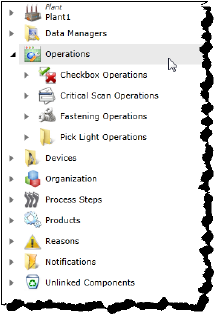
The Operations folder gathers all the Operations of four major categories that currently exist in your instance of PINpoint. These categories are:
•Checkbox Operations
•Critical Scan Operations
•Fastening Operations
•Pick Light Operations
While it is not possible to directly create components using the Operations folder itself, Operations of these four types can be created (and modified) using their respective sub-folders. As well, a large number of subcomponents can be created and modified for each kind of Operation.
Figure 225: Operations folder hierarchy
Operations — Checkbox
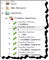
The Checkbox Operations sub-folder gathers and displays all the Checkbox Operations currently existing in your instance of PINpoint.
A Checkbox Operation is used in Processing Steps to ensure that an operation is complete by requiring confirmation input from the operator. It can have a variety of input methods as subcomponents.
Figure 226: Checkbox hierarchy
Creating a New Checkbox Operation
To create a new Checkbox Operation, follow these steps.
1.If you are not already in the SmartBuild interface, click on the Portal > SmartBuild button. The SmartBuild interface opens.
2.On the SmartBuild panel, select Advanced. The Advanced workspace opens.
3.Expand the Operations hierarchy.
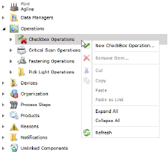
4.Right-click the Checkbox Operations icon and select New Checkbox Operation...
Figure 227: Checkbox menu
The dialog for naming the new Checkbox Operation opens.
5.Type a name for the new Checkbox Operation.
6.Click Next. The dialog for configuring the attributes of your new Checkbox Operation opens.
7.Configure the following attributes:
Refer to the table Heading3.
8.When you have completed configuring the attributes, click Finish. The new Checkbox Operation is displayed in the Checkbox Operations folder, and is available for use by Process Steps.
Creating New Sub-components for Checkbox Operations
To create a new component for a Checkbox Operation, follow these steps.
1.If you are not already in the SmartBuild interface, click on the Portal > SmartBuild button. The SmartBuild interface opens.
2.On the SmartBuild panel, select Advanced. The Advanced workspace opens.
3.Expand the Operations hierarchy.
4.Expand the Checkbox Operations hierarchy and locate the Checkbox Operation you want to work with.
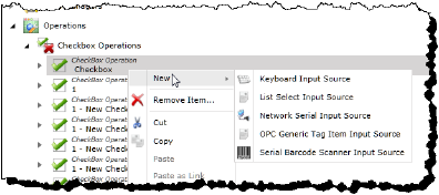
5.Right-click the Checkbox Operation icon and hover the mouse pointer over New to view the options. Select the component you want to create.
Figure 228: Checkbox Operations menu
The dialog for naming the component type you selected opens.
6.Type a name for the new component.
7.Click Next. The dialog for configuring the attributes of your new component opens.
You can use the following table to reference the list of your component’s attributes and descriptions of their purposes, if required.
Table 43: Component attribute lookup links
|
|
8.When you have completed configuring the attributes, click Finish. The new component is displayed in the Checkbox Operation folder.
Editing Existing Components
To edit existing components organized in the Checkbox Operations hierarchy, follow these steps.
1.If you are not already in the SmartBuild interface, click on the Portal > SmartBuild button. The SmartBuild interface opens.
2.On the SmartBuild panel, select Advanced. The Advanced workspace opens.
3.Expand the Operations hierarchy.
4.Expand the Checkbox Operations hierarchy, and those of any subcomponents necessary, and locate the component whose attributes you want to edit.
5.Select the component. Its attributes populate the Details pane.
6.Make the changes you require to the component’s attributes.
You can use the following table to reference the list of your component’s attributes and descriptions of their purposes, if required.
Table 44: Component attribute lookup links
7.When you have completed configuring the attributes, click Save. The component’s updated attributes are applied.
Operations — Critical Scan Operations
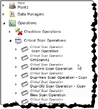
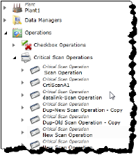
The Critical Scan Operations sub-folder gathers and displays all the Critical Scan Operations currently existing in your instance of PINpoint.
A Critical Scan Operation is one configured to ensure that an input is within certain bounds. It can be activated by the operator using a touch screen or a mouse. They can also be linked to an input from an OPC tag. It can have a variety of input methods as subcomponents.
Figure 229: Critical Scan hierarchy
Creating a New Critical Scan Operation
To create a new Critical Scan Operation, follow these steps.
1.If you are not already in the SmartBuild interface, click on the Portal > SmartBuild button. The SmartBuild interface opens.
2.On the SmartBuild panel, select Advanced. The Advanced workspace opens.
3.Expand the Operations hierarchy.
4.Right-click the Critical Scan Operations icon and select New Critical Scan Operation...
Figure 230: Critical Scan menu
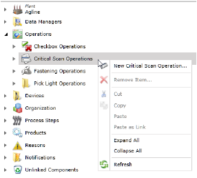
The dialog for naming the new Critical Scan Operation opens.
5.Type a name for the new Critical Scan Operation.
6.Click Next. The dialog for configuring the attributes of your new Critical Scan Operation opens.
7.Configure the following attributes:
Refer to the table Heading3.
8.When you have completed configuring the attributes, click Finish. The new Critical Scan Operation is displayed in the Critical Scan Operations folder, and is available for use by Process Steps.
Creating New Sub-components for Critical Scan Operations
To create a new component for a Critical Scan Operation, follow these steps.
1.If you are not already in the SmartBuild interface, click on the Portal > SmartBuild button. The SmartBuild interface opens.
2.On the SmartBuild panel, select Advanced. The Advanced workspace opens.
3.Expand the Operations hierarchy.
4.Expand the Critical Scan Operations hierarchy and locate the Critical Scan Operation you want to work with.
5.Right-click the Critical Scan Operation icon and hover the mouse pointer over New to view the options. Select the component you want to create.
Figure 231: Critical Scan Operation menu
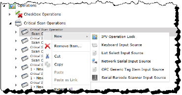
The dialog for naming the component type you selected opens.
6.Type a name for the new component.
7.Click Next. The dialog for configuring the attributes of your new component opens.
You can use the following table to reference the list of your component’s attributes and descriptions of their purposes, if required.
Table 45: Component attribute lookup links
8.When you have completed configuring the attributes, click Finish. The new component is displayed in the Critical Scan Operation folder.
Editing Existing Components
To edit existing components organized in the Critical Scan Operations hierarchy, follow these steps.
1.If you are not already in the SmartBuild interface, click on the Portal > SmartBuild button. The SmartBuild interface opens.
2.On the SmartBuild panel, select Advanced. The Advanced workspace opens.
3.Expand the Operations hierarchy.
4.Expand the Critical Scan Operations hierarchy, and those of any subcomponents necessary, and locate the component whose attributes you want to edit.
5.Select the component. Its attributes populate the Details pane.
6.Make the changes you require to the component’s attributes.
You can use the following table to reference the list of your component’s attributes and descriptions of their purposes, if required.
Table 46: Component attribute lookup links
|
|
7.When you have completed configuring the attributes, click Save. The component’s updated attributes are applied.
Operations — Fastening Operations
The Fastening Operations sub-folder gathers and displays all the Fastening Operations currently existing in your instance of PINpoint.
A Fastening Operation lists the conditions which must be met by the fastening tool in its Process Step. It can have a variety of Fastening Tools as subcomponents.
Figure 232: Fastening hierarchy
Creating a New Fastening Operation
To create a new Fastening Operation, follow these steps.
1.If you are not already in the SmartBuild interface, click on the Portal > SmartBuild button. The SmartBuild interface opens.
2.On the SmartBuild panel, select Advanced. The Advanced workspace opens.
3.Expand the Operations hierarchy.
4.Right-click the Fastening Operations icon and select New Fastening Operation...
Figure 233: Fastening Menu
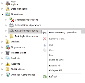
The dialog for naming the new Fastening Operation opens.
5.Type a name for the new Fastening Operation.
6.Click Next. The dialog for configuring the attributes of your new Fastening Operation opens.
7.Configure the following attributes:
Refer to the table Heading3.
8.When you have completed configuring the attributes, click Finish. The new Fastening Operation is displayed in the Fastening Operations folder, and is available for use by Process Steps.
Creating New Sub-components for Fastening Operations
To create a new component for a Fastening Operation, follow these steps.
1.If you are not already in the SmartBuild interface, click on the Portal > SmartBuild button. The SmartBuild interface opens.
2.On the SmartBuild panel, select Advanced. The Advanced workspace opens.
3.Expand the Operations hierarchy.
4.Expand the Fastening Operations hierarchy and locate the Fastening Operation you want to work with.
5.Right-click the Fastening Operation icon and hover the mouse pointer over New to view the options. Select the component you want to create.
Figure 234: Fastening Operation menu
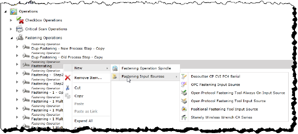
The dialog for naming the component type you selected opens.
6.Type a name for the new component.
7.Click Next. The dialog for configuring the attributes of your new component opens.
You can use the following table to reference the list of your component’s attributes and descriptions of their purposes, if required.
Table 47: Component attribute lookup links
|
|
8.When you have completed configuring the attributes, click Finish. The new component is displayed in the Fastening Operation folder.
Editing Existing Components
To edit existing components organized in the Fastening Operations hierarchy, follow these steps.
1.If you are not already in the SmartBuild interface, click on the Portal > SmartBuild button. The SmartBuild interface opens.
2.On the SmartBuild panel, select Advanced. The Advanced workspace opens.
3.Expand the Operations hierarchy.
4.Expand the Fastening Operations hierarchy, and those of any subcomponents necessary, and locate the component whose attributes you want to edit.
5.Select the component. Its attributes populate the Details pane.
6.Make the changes you require to the component’s attributes.
You can use the following table to reference the list of your component’s attributes and descriptions of their purposes, if required.
Table 48: Component attribute lookup links
7.When you have completed configuring the attributes, click Save. The component’s updated attributes are applied.
Operations — Pick Light Operations
The Pick Light Operations sub-folder gathers and displays all the Pick Light Operations currently existing in your instance of PINpoint.
A Pick Light Operation lists the conditions which must be met by the Pick Light tool in its Process Step. It can have a Pick Light Input Source as a subcomponent.
Figure 235: Pick Light hierarchy
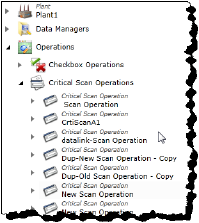
Creating a New Pick Light Operation
To create a new Pick Light Operation, follow these steps.
1.If you are not already in the SmartBuild interface, click on the Portal > SmartBuild button. The SmartBuild interface opens.
2.On the SmartBuild panel, select Advanced. The Advanced workspace opens.
3.Expand the Operations hierarchy.
4.Right-click the Pick Light Operations icon and select New Pick Light Operation...
Figure 236: Picklight Menu
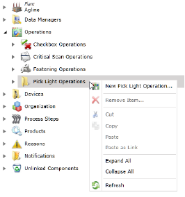
The dialog for naming the new Pick Light Operation opens.
5.Type a name for the new Pick Light Operation.
6.Click Next. The dialog for configuring the attributes of your new Pick Light Operation opens.
7.Configure the following attributes:
Refer to the table Heading3.
8.When you have completed configuring the attributes, click Finish. The new Pick Light Operation is displayed in the Pick Light Operations folder, and is available for use by Process Steps.
Creating a New Pick Light Input Source to a Pick Light Operations
To create a new Pick Light Input Source for a Pick Light Operation, follow these steps.
1.If you are not already in the SmartBuild interface, click on the Portal > SmartBuild button. The SmartBuild interface opens.
2.On the SmartBuild panel, select Advanced. The Advanced workspace opens.
3.Expand the Operations hierarchy.
4.Expand the Pick Light Operations hierarchy and locate the Pick Light Operation you want to work with.
5.Right-click the Pick Light Operation icon and New Pick Light Input Source....
Figure 237: New Pick Light Operation menu
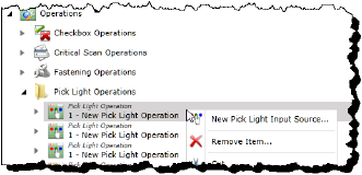
The dialog for naming the Pick Light Input Source opens.
6.Type a name for the new Pick Light Input Source.
7.Click Next. The dialog for configuring the attributes of your new Pick Light Input Source opens.
Refer to the table Heading3.
8.When you have completed configuring the attributes, click Finish. The new Pick Light Input Source is displayed in the Pick Light Operation folder.
Editing Existing Components
To edit existing components organized in the Pick Light Operations hierarchy, follow these steps.
1.If you are not already in the SmartBuild interface, click on the Portal > SmartBuild button. The SmartBuild interface opens.
2.On the SmartBuild panel, select Advanced. The Advanced workspace opens.
3.Expand the Operations hierarchy.
4.Expand the Pick Light Operations hierarchy, and those of any subcomponents necessary, and locate the component whose attributes you want to edit.
5.Select the component. Its attributes populate the Details pane.
6.Make the changes you require to the component’s attributes.
You can use the following table to reference the list of your component’s attributes and descriptions of their purposes, if required.
Table 49: Component attribute lookup links
7.When you have completed configuring the attributes, click Save. The component’s updated attributes are applied.
Devices Folder
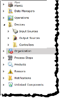
The Devices folder gathers all the Devices of four major categories that currently exist in your instance of PINpoint. These categories are:
•Input Sources
•Output Sources
•Controllers
While it is not possible to directly create components using the Devices folder itself, Devices of these four categories can be created (and modified) using their respective sub-folders. As well, a large number of subcomponents can be created and modified for each category of Device.
Figure 238: Devices folder hierarchy
Devices — Input Sources
The Input Sources sub-folder gathers and displays all the Input Sources currently existing in your instance of PINpoint.
An Input Source is used to provide information, either from an operator or a process on the line, to PINpoint to be communicated to its systems or to users.
Creating a New Input Source
To create a new Input Source, follow these steps.
1.If you are not already in the SmartBuild interface, click on the Portal > SmartBuild button. The SmartBuild interface opens.
2.On the SmartBuild panel, select Advanced. The Advanced workspace opens.
3.Expand the Devices hierarchy.
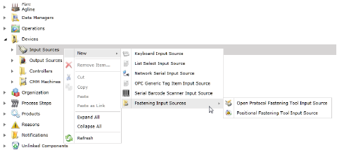
4.Right-click the Input Sources icon and hover the mouse pointer over New to view the options. Select the component you want to create.
Figure 239: Input Sources menu
The dialog for naming the component type you selected opens.
5.Type a name for the new component.
6.Click Next. The dialog for configuring the attributes of your new component opens.
You can use the following table to reference the list of your component’s attributes and descriptions of their purposes, if required.
Table 50: Component attribute lookup links
|
|
7.When you have completed configuring the attributes, click Finish. The new component is displayed in the Input Sources folder.
Creating New Sub-components for Input Sources
To create a new component for an Input Source, follow these steps.
1.If you are not already in the SmartBuild interface, click on the Portal > SmartBuild button. The SmartBuild interface opens.
2.On the SmartBuild panel, select Advanced. The Advanced workspace opens.
3.Expand the Devices hierarchy.
4.Expand the Input Sources hierarchy and locate the Input Source category folder you want to work with.
5.Right-click the folder icon and select the component you want to create.
The dialog for naming the component type you selected opens.
6.Type a name for the new component.
7.Click Next. The dialog for configuring the attributes of your new component opens.
You can use the following table to reference the list of your component’s attributes and descriptions of their purposes, if required.
Table 51: Component attribute lookup links
8.When you have completed configuring the attributes, click Finish. The new component is displayed in the Input Sources folder.
Editing Existing Components
To edit existing components organized in the Input Sources hierarchy, follow these steps.
1.If you are not already in the SmartBuild interface, click on the Portal > SmartBuild button. The SmartBuild interface opens.
2.On the SmartBuild panel, select Advanced. The Advanced workspace opens.
3.Expand the Devices hierarchy.
4.Expand the Input Sources hierarchy, and those of any subcomponents necessary, and locate the component whose attributes you want to edit.
5.Select the component. Its attributes populate the Details pane.
6.Make the changes you require to the component’s attributes.
You can use the following table to reference the list of your component’s attributes and descriptions of their purposes, if required.
Table 52: Component attribute lookup links
7.When you have completed configuring the attributes, click Save. The component’s updated attributes are applied.
NoteWhenever you make changes to the configuration of a device, that device needs to be stopped, its configuration reloaded, and restarted. This is done using the Dashboard functionality of SmartBuild. For more information, see Heading4.
Devices — Output Devices
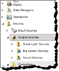
The Output Sources sub-folder gathers and displays all the Output Sources currently existing in your instance of PINpoint.
An Output Source is used to provide information about conditions to users, operators, and managers on the line.
Figure 240: Output Sources hierarchy
Creating a New Output Source
To create a new Output Source, follow these steps.
1.If you are not already in the SmartBuild interface, click on the Portal > SmartBuild button. The SmartBuild interface opens.
2.On the SmartBuild panel, select Advanced. The Advanced workspace opens.
3.Expand the Devices hierarchy.
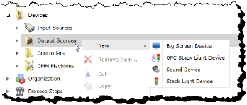
4.Right-click the Output Sources icon and select the component you want to create.
Figure 241: Output Sources menu
The dialog for naming the component type you selected opens.
5.Type a name for the new component.
6.Click Next. The dialog for configuring the attributes of your new component opens.
You can use the following table to reference the list of your component’s attributes and descriptions of their purposes, if required.
Table 53: Component attribute lookup links
7.When you have completed configuring the attributes, click Finish. The new component is displayed in the Output Sources folder.
Creating New Sub-components for Output Sources
Sub-components can be added to BigScreens in the BigScreen’s folder. To create a new component for a BigScreen, follow these steps.
1.If you are not already in the SmartBuild interface, click on the Portal > SmartBuild button. The SmartBuild interface opens.
2.On the SmartBuild panel, select Advanced. The Advanced workspace opens.
3.Expand the Devices hierarchy.
4.Expand the Output Sources hierarchy.
5.Expand the BigScreens hierarchy and locate the BigScreen device you want to work with.
6.Right-click the BigScreen device icon and select the component you want to create.
Figure 242: BigScreen components menu
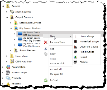
The dialog for naming the component type you selected opens.
7.Type a name for the new component.
8.Click Next. The dialog for configuring the attributes of your new component opens.
You can use the following table to reference the list of your component’s attributes and descriptions of their purposes, if required.
Table 54: Component attribute lookup links
9.When you have completed configuring the attributes, click Finish. The new component is displayed in the Output Sources folder.
Editing Existing Components
To edit existing components organized in the Output Sources hierarchy, follow these steps.
1.If you are not already in the SmartBuild interface, click on the Portal > SmartBuild button. The SmartBuild interface opens.
2.On the SmartBuild panel, select Advanced. The Advanced workspace opens.
3.Expand the Devices hierarchy.
4.Expand the Output Sources hierarchy, and those of any subcomponents necessary, and locate the component whose attributes you want to edit.
5.Select the component. Its attributes populate the Details pane.
6.Make the changes you require to the component’s attributes.
You can use the following table to reference the list of your component’s attributes and descriptions of their purposes, if required.
Table 55: Component attribute lookup links
7.When you have completed configuring the attributes, click Save. The component’s updated attributes are applied.
NoteWhenever you make changes to the configuration of a device, that device needs to be stopped, its configuration reloaded, and restarted. This is done using the Dashboard functionality of SmartBuild. For more information, see Heading4.
Devices — Controllers
The Controllers sub-folder gathers and displays all the Controllers currently existing in your instance of PINpoint.
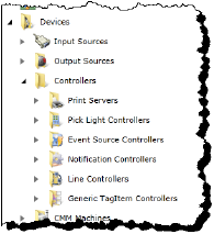
A Controller is used to manage the interaction and behavior of various hardware on the production line.
Figure 243: Controllers hierarchy
Creating a New Controller
To create a new Controller, follow these steps.
1.If you are not already in the SmartBuild interface, click on the Portal > SmartBuild button. The SmartBuild interface opens.
2.On the SmartBuild panel, select Advanced. The Advanced workspace opens.
3.Expand the Devices hierarchy.
4.Expand the Controllers hierarchy.
5.Right-click the icon of the Controller type you want to create and select the component you want to create.
Figure 244: Controllers menu
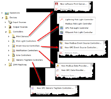
The dialog for naming the component type you selected opens.
6.Type a name for the new component.
7.Click Next. The dialog for configuring the attributes of your new component opens.
You can use the following table to reference the list of your component’s attributes and descriptions of their purposes, if required.
Table 56: Component attribute lookup links
|
|
8.When you have completed configuring the attributes, click Finish. The new component is displayed in the Controllers folder.
Creating New Sub-components for Controllers
Sub-components can be added to BigScreens in the BigScreen’s folder. To create a new component for a BigScreen, follow these steps.
1.If you are not already in the SmartBuild interface, click on the Portal > SmartBuild button. The SmartBuild interface opens.
2.On the SmartBuild panel, select Advanced. The Advanced workspace opens.
3.Expand the Devices hierarchy.
4.Expand the Controllers hierarchy.
5.Expand the hierarchy of the Controller type and locate the Controller you want to work with.
6.Right-click the Controller icon and select the component you want to create.
The dialog for naming the component type you selected opens.
7.Type a name for the new component.
8.Click Next. The dialog for configuring the attributes of your new component opens.
You can use the following table to reference the list of your component’s attributes and descriptions of their purposes, if required.
Table 57: Component attribute lookup links
9.When you have completed configuring the attributes, click Finish. The new component is displayed in the Controller’s folder.
Editing Existing Components
To edit existing components organized in the Controllers hierarchy, follow these steps.
1.If you are not already in the SmartBuild interface, click on the Portal > SmartBuild button. The SmartBuild interface opens.
2.On the SmartBuild panel, select Advanced. The Advanced workspace opens.
3.Expand the Devices hierarchy.
4.Expand the Controllers hierarchy, and those of any subcomponents necessary, and locate the component whose attributes you want to edit.
5.Select the component. Its attributes populate the Details pane.
6.Make the changes you require to the component’s attributes.
You can use the following table to reference the list of your component’s attributes and descriptions of their purposes, if required.
Table 58: Component attribute lookup links
7.When you have completed configuring the attributes, click Save. The component’s updated attributes are applied.
NoteWhenever you make changes to the configuration of a device, that device needs to be stopped, its configuration reloaded, and restarted. This is done using the Dashboard functionality of SmartBuild. For more information, see Heading4.
Organization Folder
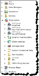
The Organization folder provides access to a variety of components, enabling you to create and modify them and their related sub-components.
Figure 245: Organization hierarchy
Creating New Components in the Organization Folder
To create new components directly in the Organization folder, follow these steps.
1.If you are not already in the SmartBuild interface, click on the Portal > SmartBuild button. The SmartBuild interface opens.
2.On the SmartBuild panel, select Advanced. The Advanced workspace opens.
3.Right-click the Organization icon and select the component you want to create.
Figure 246: Organization menu
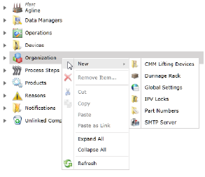
The dialog for naming the component type you selected opens.
4.Type a name for the new component.
5.Click Next. The dialog for configuring the attributes of your new component opens.
You can use the following table to reference the list of your component’s attributes and descriptions of their purposes, if required.
Table 59: Component attribute lookup links
|
|
6.When you have completed configuring the attributes, click Finish. The new component is displayed in the Organization folder.
Organization Folder — SMTP Server
SMTP Servers cannot be created in the Organization folder, but the components they contain can be edited. To edit them, follow these steps.
Editing an SMTP Server component
1.If you are not already in the SmartBuild interface, click on the Portal > SmartBuild button. The SmartBuild interface opens.
2.On the SmartBuild panel, select Advanced. The Advanced workspace opens.
3.Expand the Organization hierarchy.
4.Expand the SMTP Server hierarchy containing the component you want to edit.
5.Select the component. Its attributes populate the Details pane.
6.Make the changes you require to the component’s attributes.
You can use the following table to reference the list of your component’s attributes and descriptions of their purposes, if required.
Table 60: Component attribute lookup links
7.When you have completed configuring the attributes, click Save. The component’s updated attributes are applied.
Organization Folder — Email to Text Providers
Email to Text Providers are companies who facilitate the communication of email messages to the cell phones and tablets, etc., of recipients in the form of text messages received via texting client applications. These are useful in sending Event messages requiring a quick response from users and managers.
Information about text providers is stored in the form of Listbox Items.
Creating an Email to Text Providers Listbox Item
To create a new Email to Text Provider Listbox Item, follow these steps.
1.If you are not already in the SmartBuild interface, click on the Portal > SmartBuild button. The SmartBuild interface opens.
2.On the SmartBuild panel, select Advanced. The Advanced workspace opens.
3.Expand the Organization hierarchy.
4.Right-click the Email to Text Providers folder and select New Listbox Item....
Figure 247: Email to Text Providers menu

The dialog for naming the new Listbox Item opens.
5.Type a name for the new Listbox Item.
6.Click Next. The dialog for configuring the attributes of your new Listbox Item opens.
7.Configure the following attributes:
Refer to the table Heading3.
8.When you have completed configuring the attributes, click Finish. The new Listbox Item is displayed in the Email to Text Providers folder.
Editing an Email to Text Providers Listbox Item
To edit an existing Email to Text Provider Listbox Item, follow these steps.
1.If you are not already in the SmartBuild interface, click on the Portal > SmartBuild button. The SmartBuild interface opens.
2.On the SmartBuild panel, select Advanced. The Advanced workspace opens.
3.Expand the Organization hierarchy.
4.Expand the Email to Text Providers hierarchy.
5.Select the Listbox Item representing the provider you want to edit. Its attributes populate the Details pane.
6.Make the changes you require to the component’s attributes.
Refer to the table Heading3.
7.When you have completed editing the attributes, click Save. The component’s updated attributes are applied.
Organization — Global Settings
The Global Settings icon makes the various settings, applied across the system, available for modification. To modify Global Settings, follow these steps.
1.If you are not already in the SmartBuild interface, click on the Portal > SmartBuild button. The SmartBuild interface opens.
2.On the SmartBuild panel, select Advanced. The Advanced workspace opens.
3.Expand the Organization hierarchy.
4.Select the Global Settings icon. Its attributes populate the Details pane.
5.Make the changes you require to the component’s attributes.
Refer to the table Heading3.
6.When you have completed editing the attributes, click Save. The updated Global Settings attributes are applied.
Organization — Dunnage Rack
In the context of PINpoint, a Dunnage Rack is an item for organizing the Pick Light apparatuses and their associated containers at a Station, and the Pick Light Operations that reference them.
Figure 248: Dunnage Rack menu
Creating a New Dunnage Rack
To create a new Dunnage Rack, follow these steps.
1.If you are not already in the SmartBuild interface, click on the Portal > SmartBuild button. The SmartBuild interface opens.
2.On the SmartBuild panel, select Advanced. The Advanced workspace opens.
3.Right-click the Organization icon and select New > Dunnage Rack.
Figure 249: Organization menu

The dialog for naming the new Dunnage Rack you selected opens.
4.Type a name for the new component.
5.Click Next. The dialog for configuring the attributes of your new Dunnage Rack opens.
6.Configure the following attributes:
Refer to the table Heading3.
7.When you have completed configuring the attributes, click Finish. The new Dunnage Rack is displayed in the Organization folder.
Creating New Components in a Dunnage Rack
The only component that can be directly created in a Dunnage Rack is a Pick Light Operation. To create a new Pick Light Operation in the Dunnage Rack, follow these steps.
1.If you are not already in the SmartBuild interface, click on the Portal > SmartBuild button. The SmartBuild interface opens.
2.On the SmartBuild panel, select Advanced. The Advanced workspace opens.
3.Expand the Organization hierarchy.
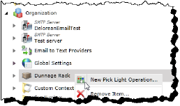
4.Right-click the Dunnage Rack folder in which you want to create a new Pick Light Operation and select New Pick Light Operation....
Figure 250: New Pick Light Operation
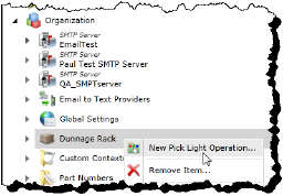
The dialog for naming the new Pick Light Operation opens.
5.Type a name for the new Pick Light Operation.
6.Click Next. The dialog for configuring the attributes of your new Pick Light Operation opens.
7.Configure the following attributes:
PRefer to the table Heading3.
8.When you have completed configuring the attributes, click Finish. The new Pick Light Operation is displayed in the Dunnage Rack folder.
Creating New Sub-components in a Dunnage Rack
The only sub-component that can be created in a Dunnage Rack is a Pick Light Input Source. To create a new Pick Light Input Source in the Pick Light Operation, follow these steps.
1.If you are not already in the SmartBuild interface, click on the Portal > SmartBuild button. The SmartBuild interface opens.
2.On the SmartBuild panel, select Advanced. The Advanced workspace opens.
3.Expand the Organization hierarchy.
4.Expand the Dunnage Rack folder in which you want to create a new Pick Light Input Source.
5.Right-click the Pick Light Operation in which you want to create a new Pick Light Input Source and select New Pick Light Input Source....
Figure 251: New Pick Light Input Source
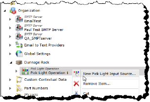
The dialog for naming the new Pick Light Input Source opens.
6.Type a name for the new Pick Light Input Source.
7.Click Next. The dialog for configuring the attributes of your new Pick Light Input Source opens.
8.Configure the following attributes:
Refer to the table Heading3.
9.When you have completed configuring the attributes, click Finish. The new Pick Light Input Source is displayed in the Pick Light Operation folder.
Editing Existing Components
To edit existing Dunnage Racks or components organized in them, follow these steps.
1.If you are not already in the SmartBuild interface, click on the Portal > SmartBuild button. The SmartBuild interface opens.
2.On the SmartBuild panel, select Advanced. The Advanced workspace opens.
3.Expand the Organization hierarchy to view the Dunnage Rack. Optionally, expand its hierachy to access any subcomponents necessary. Locate the component whose attributes you want to edit.
4.Select the component. Its attributes populate the Details pane.
5.Make the changes you require to the component’s attributes.
You can use the following table to reference the list of your component’s attributes and descriptions of their purposes, if required.
Table 61: Component attribute lookup links
|
|
6.When you have completed configuring the attributes, click Save. The component’s updated attributes are applied.
Organization — Custom Contextual Data
Contextual Data can be attached to a Product to follow it through the life cycle of its production. It can be useful in advising workers along the way of specific conditions that will apply to a particular instance of a Product. For example, a Work Order might specify the production of two identical engines, but the Contextual Data attached to one engine might designate it is destined for Germany, while the Contextual Data attached to the other might designate it is destined for Egypt. This context could imply different testing standards for each engine at the end of its production. The ability to include this Contextual Data spares a facility from having to create a different copy of every product with such differences.
Adding Contextual Data to a Product
To add Custom Contextual Data to a Product, follow these steps.
1.If you are not already in the SmartBuild interface, click on the Portal > SmartBuild button. The SmartBuild interface opens.
2.On the SmartBuild panel, select Advanced. The Advanced workspace opens.
3.Expand Organization.
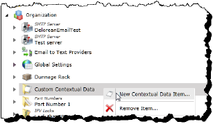
4.Right-click New Contextual Data Item... The Contextual Data Item dialog opens.
Figure 252: Custom Contextual Data menu
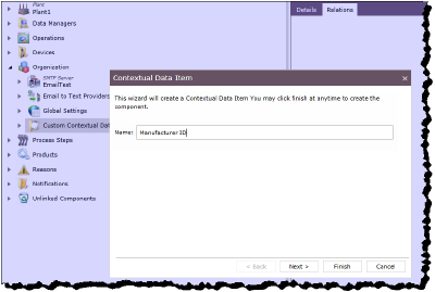
5.Type a name for the new Contextual Data Item.
Figure 253: Contextual Data Item dialog
6.Click Next. The Contextual Data Item dialog displays the Component Attributes attributes.
Figure 254: Contextual Data Item attributes
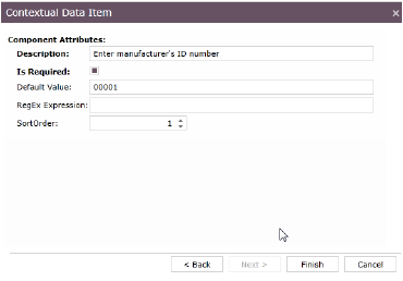
Refer to the table Heading3.
7.Click Finish. The new Contextual Data Item appears in the Custom Contextual Data folder.
8.If necessary, expand the Custom Contextual Data folder to view the new Contextual Data Item.
9.Click the new Contextual Data Item to select it.
10.If necessary, select the Relations tab.
Figure 255: Relations tab
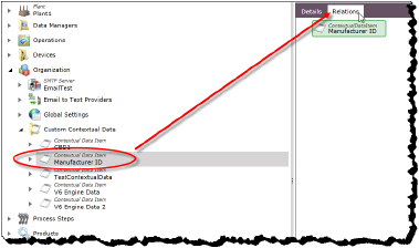
11.Right-click the Contextual Data Item and select Add Children...
Figure 256: Add Children to Contextual Data Item
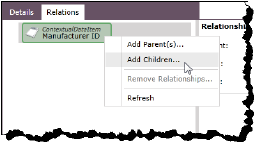
The Add New Relationships dialog opens.
Figure 257: Add New Relationships dialog
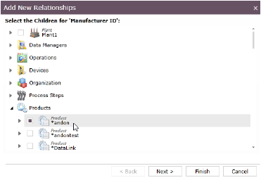
12.Expand Products.
13.Use the check boxes to select the Product or Products to which the Contextual Data Item will be added.
14.Click Next. A confirmation of the Product(s) you are assigning to the Contextual Data Item is displayed.
15.Click Finish. The Product or Products are displayed in the Contextual Data Item’s hierarchy. This Contextual Data will be available for use with the Product(s) when Work Orders are created.
Removing Contextual Data from a Product
To remove an instance of Contextual Data from a Product, technically, the Product is removed from the Contextual Data Item’s hierarchy. To do this, follow these steps.
1.If you are not already in the SmartBuild interface, click on the Portal > SmartBuild button. The SmartBuild interface opens.
2.On the SmartBuild panel, select Advanced. The Advanced workspace opens.
3.Expand Organization > Custom Contextual Data.
4.Select the Contextual Data Item with the Product you want to remove from it.
5.If necessary, select the Relations tab.
6.In the hierarchy of the Contextual Data Item, right-click the Product you no longer want associated with this Contextual Data and select Remove Relationships...
Figure 258: Remove Relationships... option
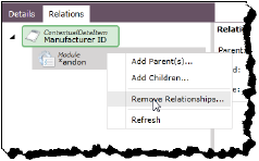
The Remove Relationship dialog opens.
7.Click Yes to confirm the deletion of the relationship. The Product is removed from the Contextual Data Item’s hierarchy.
Organization — Part Numbers
In the context of PINpoint, a Part Number is an item for referencing a particular part in the system. They can be associated with Part Operations and the lifting and measuring machines used to measure them.
Figure 259: Part Numbers menu
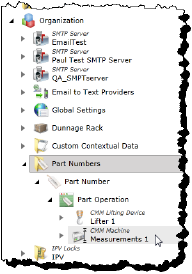
Creating a New Part Numbers Folder
To create a new Part Numbers folder, follow these steps.
1.If you are not already in the SmartBuild interface, click on the Portal > SmartBuild button. The SmartBuild interface opens.
2.On the SmartBuild panel, select Advanced. The Advanced workspace opens.
3.Right-click the Organization icon and select New > Part Numbers.
Figure 260: Organization menu

The dialog for naming the new Part Numbers folder opens.
4.Type a name for the new Part Numbers folder.
5.Click Next. The dialog for configuring the attributes of your new Part Numbers folder opens.
Configure the following attributes:
Refer to the table Heading3.
6.When you have completed configuring the attributes, click Finish. The new Part Numbers folder is displayed in the Organization folder.
Creating a New Part Number
The only component that can be directly created in a Part Numbers folder is a Part Number. To create a new Part Number, follow these steps.
1.If you are not already in the SmartBuild interface, click on the Portal > SmartBuild button. The SmartBuild interface opens.
2.On the SmartBuild panel, select Advanced. The Advanced workspace opens.
3.Expand the Organization hierarchy.
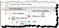
4.Right-click the Part Numbers folder in which you want to create a new Part Number and select New Part Number....
Figure 261: New Part Number
The dialog for naming the new Part Number opens.
5.Type a name for the new Part Number.
6.Click Next. The dialog for configuring the attributes of your new Part Number opens.
7.Configure the following attributes:
Refer to the table Heading3.
8.When you have completed configuring the attributes, click Finish. The new Part Number is displayed in the Part Numbers folder.
Creating New Sub-components in a Part Number
A Part Operation sub-component can be created for a Part Number.
Creating a New Part Operation
To create a new Part Operation, follow these steps.
1.If you are not already in the SmartBuild interface, click on the Portal > SmartBuild button. The SmartBuild interface opens.
2.On the SmartBuild panel, select Advanced. The Advanced workspace opens.
3.Expand the Organization hierarchy.
4.Expand the Part Numbers folder.
5.Right-click the Part Number for which you want to create a new Part Operation and select New Part Operation....
Figure 262: New Part Operation

The dialog for naming the new Part Operation opens.
6.Type a name for the new Part Operation.
7.Click Next. The dialog for configuring the attributes of your new Part Operation opens.
8.Configure the following attributes:
Refer to the table Heading3.
9.When you have completed configuring the attributes, click Finish. The new Part Operation is displayed in the Part Number hierarchy.
Editing Existing Components
To edit an existing Part Numbers folder or the components organized in it, follow these steps.
1.If you are not already in the SmartBuild interface, click on the Portal > SmartBuild button. The SmartBuild interface opens.
2.On the SmartBuild panel, select Advanced. The Advanced workspace opens.
3.Expand the Organization hierarchy to view the Part Numbers. Optionally, expand its hierarchy to access any subcomponents necessary. Locate the component whose attributes you want to edit.
4.Select the component. Its attributes populate the Details pane.
5.Make the changes you require to the component’s attributes.
You can use the following table to reference the list of your component’s attributes and descriptions of their purposes, if required.
Table 62: Component attribute lookup links
|
|
6.When you have completed configuring the attributes, click Save. The component’s updated attributes are applied.
Organization — IPV Locks
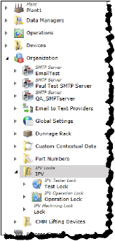
An IPV (In Process Validation) Lock is utilized when an operator makes a bad rundown (Level 1) or certain number of consecutive bad rundowns (Level 2), which cause the tool being used to be locked. In some circumstances, an IPV Lock may be triggered that is plant-wide (Level 3). Level 1 locks can be cleared by the operator at the station, but Levels 2 and 3 require an LCA to clear them.
Figure 263: IPV Locks hierarchy
Creating a New IPV Locks Folder
To create a new IPV Locks folder, follow these steps.
1.If you are not already in the SmartBuild interface, click on the Portal > SmartBuild button. The SmartBuild interface opens.
2.On the SmartBuild panel, select Advanced. The Advanced workspace opens.
3.Right-click the Organization icon and select New > IPV Locks.
Figure 264: Organization menu

The dialog for naming the new IPV Locks folder opens.
4.Type a name for the new IPV Locks folder.
5.Click Next. The dialog for configuring the attributes of your new IPV Locks folder opens.
Configure the following attributes:
Refer to the table Heading3.
6.When you have completed configuring the attributes, click Finish. The new IPV Locks folder is displayed in the Organization folder.
Creating a New Component
To create a new component in an IPV Locks folder, follow these steps.
1.If you are not already in the SmartBuild interface, click on the Portal > SmartBuild button. The SmartBuild interface opens.
2.On the SmartBuild panel, select Advanced. The Advanced workspace opens.
3.Expand the Organization hierarchy.
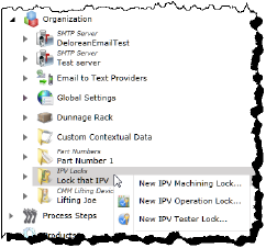
4.Right-click the IPV Parts folder in which you want to create a new component and select the component you want to create.
Figure 265: IPV Locks menu
The dialog for naming the new component opens.
5.Type a name for the new component.
6.Click Next. The dialog for configuring the attributes of your new component opens.
You can use the following table to reference the list of your component’s attributes and descriptions of their purposes, if required.
Table 63: Component attribute lookup links
|
|
7.When you have completed configuring the attributes, click Finish. The new component is displayed in the IPV Locks folder.
Editing Existing Components
To edit an existing IPV Locks folder or the components organized in it, follow these steps.
1.If you are not already in the SmartBuild interface, click on the Portal > SmartBuild button. The SmartBuild interface opens.
2.On the SmartBuild panel, select Advanced. The Advanced workspace opens.
3.Expand the Organization hierarchy to view the IPV Locks. Optionally, expand its hierarchy to access any subcomponents necessary. Locate the component whose attributes you want to edit.
4.Select the component. Its attributes populate the Details pane.
5.Make the changes you require to the component’s attributes.
You can use the following table to reference the list of your component’s attributes and descriptions of their purposes, if required.
Table 64: Component attribute lookup links
6.When you have completed configuring the attributes, click Save. The component’s updated attributes are applied.
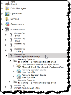
The Process Steps folder gathers all the Process Steps that currently exist in your PINpoint system, and makes them and the components related to them easily available for viewing and editing. As well, the folder enables you to create new Process Steps and components for them.
Figure 266: Process Steps hierarchy
Creating New Process Steps in the Process Steps Folder
To create new Process Steps the Process Steps folder, follow these steps.
1.If you are not already in the SmartBuild interface, click on the Portal > SmartBuild button. The SmartBuild interface opens.
2.On the SmartBuild panel, select Advanced. The Advanced workspace opens.
3.Right-click the Process Steps icon and select New Process Step....
Figure 267: Process Steps menu
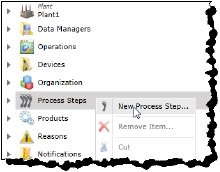
The dialog for naming the new Process Step opens.
4.Type a name for the new component.
5.Click Next. The dialog for configuring the attributes of your new Process Step opens.
Refer to the table Heading3.
6.When you have completed configuring the attributes, click Finish. The new component is displayed in the Organization folder.
Creating New Sub-components for Process Steps
Sub-components can be added to Process Steps in the Process Steps folder. To create a new component for a Process Step, follow these steps.
1.If you are not already in the SmartBuild interface, click on the Portal > SmartBuild button. The SmartBuild interface opens.
2.On the SmartBuild panel, select Advanced. The Advanced workspace opens.
3.Right-click the Process Steps icon and select the component you want to create.
Figure 268: Process Step Operation menu
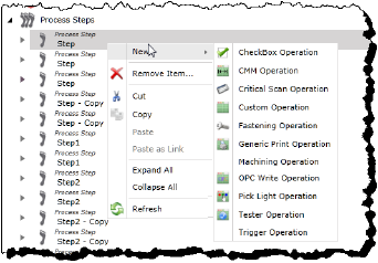
The dialog for naming the component type you selected opens.
4.Type a name for the new component.
5.Click Next. The dialog for configuring the attributes of your new component opens.
You can use the following table to reference the list of your component’s attributes and descriptions of their purposes, if required.
Table 65: Component attribute lookup links
|
|
6.When you have completed configuring the attributes, click Finish. The new component is displayed in the Process Step’s folder.
Editing Existing Process Steps
To create new Process Steps the Process Steps folder, follow these steps.
1.If you are not already in the SmartBuild interface, click on the Portal > SmartBuild button. The SmartBuild interface opens.
2.On the SmartBuild panel, select Advanced. The Advanced workspace opens.
3.Expand the Process Steps folder.
4.Select the component. Its attributes populate the Details pane.
5.Make the changes you require to the component’s attributes.
Refer to the table Heading3.
6.When you have completed editing the attributes, click Save. The Process Step’s updated attributes are applied.
Process Steps — Checkbox Operation
A Checkbox Operation is used in Processing Steps to ensure that an operation is complete by requiring confirmation input from the operator. It can have a variety of input methods as subcomponents.
Creating New Checkbox Operations for Process Steps
To create a new Checkbox Operation for a Process Step, follow these steps.
1.If you are not already in the SmartBuild interface, click on the Portal > SmartBuild button. The SmartBuild interface opens.
2.On the SmartBuild panel, select Advanced. The Advanced workspace opens.
3.Expand the Process Steps folder and locate the Process Step for which you want to create a new Checkbox Operation.
4.Right-click the Process Steps icon and select New > Checkbox Operation.
Figure 269: Process Step Operation menu

The dialog for naming the Checkbox Operation opens.
5.Type a name for the new Checkbox Operation.
6.Click Next. The dialog for configuring the attributes of your new Checkbox Operation opens.
7.Configure the following attributes:
Refer to the table Heading3.
8.When you have completed configuring the attributes, click Finish. The new component is displayed in the Process Step’s folder.
Creating New Sub-components for Checkbox Operations
Sub-components can be added to a Checkbox Operation. To create a new component for a Checkbox Operation, follow these steps.
1.If you are not already in the SmartBuild interface, click on the Portal > SmartBuild button. The SmartBuild interface opens.
2.On the SmartBuild panel, select Advanced. The Advanced workspace opens.
3.Expand the Process Steps folder and locate the Checkbox Operation to which you want to add a component.
4.Right-click the Checkbox Operation and select the component you want to create.
Figure 270: Checkbox Operation menu
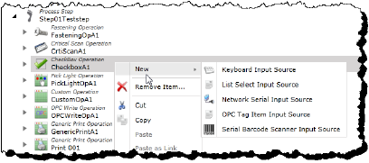
The dialog for naming the component type you selected opens.
5.Type a name for the new component.
6.Click Next. The dialog for configuring the attributes of your new component opens.
You can use the following table to reference the list of your component’s attributes and descriptions of their purposes, if required.
Table 66: Component attribute lookup links
|
|
7.When you have completed configuring the attributes, click Finish. The new component is displayed in the Process Step’s folder.
Editing Existing Components
To edit an existing Checkbox Operation or the components associated with it, follow these steps.
1.If you are not already in the SmartBuild interface, click on the Portal > SmartBuild button. The SmartBuild interface opens.
2.On the SmartBuild panel, select Advanced. The Advanced workspace opens.
3.Expand the Process Steps hierarchy to view the Checkbox Operations. Optionally, expand its hierarchy to access any subcomponents necessary. Locate the component whose attributes you want to edit.
4.Select the component. Its attributes populate the Details pane.
5.Make the changes you require to the component’s attributes.
You can use the following table to reference the list of your component’s attributes and descriptions of their purposes, if required.
Table 67: Component attribute lookup links
6.When you have completed configuring the attributes, click Save. The component’s updated attributes are applied.
Process Steps — Critical Scan Operation
The Critical Scan Operations folder gathers and makes available for editing the Critical Scan Operations of a Process Step, as well as to create their related sub-components.
A Critical Scan Operation is a process for scanning information into the system using any of a variety of input devices.
Creating New Critical Scan Operations for Process Steps
To create a new Critical Scan Operation for a Process Step, follow these steps.
1.If you are not already in the SmartBuild interface, click on the Portal > SmartBuild button. The SmartBuild interface opens.
2.On the SmartBuild panel, select Advanced. The Advanced workspace opens.
3.Expand the Process Steps folder and locate the Process Step for which you want to create a new Critical Scan Operation.
4.Right-click the Process Steps icon and select New > Critical Scan Operation.
Figure 271: Process Step Operation menu

The dialog for naming the Critical Scan Operation opens.
5.Type a name for the new Critical Scan Operation.
6.Click Next. The dialog for configuring the attributes of your new Critical Scan Operation opens.
7.Configure the following attributes:
Refer to the table Heading3.
8.When you have completed configuring the attributes, click Finish. The new component is displayed in the Process Step’s folder.
Creating New Sub-components for Critical Scan Operations
Sub-components can be added to a Critical Scan Operation. To create a new component for a Critical Scan Operation, follow these steps.
1.If you are not already in the SmartBuild interface, click on the Portal > SmartBuild button. The SmartBuild interface opens.
2.On the SmartBuild panel, select Advanced. The Advanced workspace opens.
3.Expand the Process Steps folder and locate the Critical Scan Operation to which you want to add a component.
4.Right-click the Critical Scan Operation and select the component you want to create.
Figure 272: Critical Scan Operation menu

The dialog for naming the component type you selected opens.
5.Type a name for the new component.
6.Click Next. The dialog for configuring the attributes of your new component opens.
You can use the following table to reference the list of your component’s attributes and descriptions of their purposes, if required.
Table 68: Component attribute lookup links
7.When you have completed configuring the attributes, click Finish. The new component is displayed in the Process Step’s folder.
Editing Existing Components
To edit an existing Critical Scan Operation or the components associated with it, follow these steps.
1.If you are not already in the SmartBuild interface, click on the Portal > SmartBuild button. The SmartBuild interface opens.
2.On the SmartBuild panel, select Advanced. The Advanced workspace opens.
3.Expand the Process Steps hierarchy to view the Critical Scan Operations. Optionally, expand its hierarchy to access any subcomponents necessary. Locate the component whose attributes you want to edit.
4.Select the component. Its attributes populate the Details pane.
5.Make the changes you require to the component’s attributes.
You can use the following table to reference the list of your component’s attributes and descriptions of their purposes, if required.
Table 69: Component attribute lookup links
|
|
6.When you have completed configuring the attributes, click Save. The component’s updated attributes are applied.
Process Steps — Custom Operation
The Custom Operations folder gathers and makes available for editing the Custom Operations of a Process Step.
Creating New Custom Operations for Process Steps
To create a new Custom Operation for a Process Step, follow these steps.
1.If you are not already in the SmartBuild interface, click on the Portal > SmartBuild button. The SmartBuild interface opens.
2.On the SmartBuild panel, select Advanced. The Advanced workspace opens.
3.Expand the Process Steps folder and locate the Process Step for which you want to create a new Custom Operation.
4.Right-click the Process Steps icon and select New > Custom Operation.
Figure 273: Process Step Operation menu

The dialog for naming the Custom Operation opens.
5.Type a name for the new Custom Operation.
6.Click Next. The dialog for configuring the attributes of your new Custom Operation opens.
7.Configure the following attributes:
Refer to the table Heading3.
8.When you have completed configuring the attributes, click Finish. The new component is displayed in the Process Step’s folder.
Editing Existing Custom Operations
To edit an existing Custom Operation, follow these steps.
1.If you are not already in the SmartBuild interface, click on the Portal > SmartBuild button. The SmartBuild interface opens.
2.On the SmartBuild panel, select Advanced. The Advanced workspace opens.
3.Expand the Process Steps hierarchy to view the Custom Operations.
4.Select the Custom Operation. Its attributes populate the Details pane.
5.Make the changes you require to the component’s attributes.
Refer to the table Heading3.
6.When you have completed configuring the attributes, click Save. The component’s updated attributes are applied.
Process Steps — Fastening Operation
The Fastening Operations folder gathers and makes available for editing the Fastening Operations of a Process Step. It also enables you to create the sub-components related to them.
A Fastening Operation is a process for joining parts together on the production line and assuring the process is performed to specific tolerances and quantities.
Creating New Fastening Operations for Process Steps
To create a new Fastening Operation for a Process Step, follow these steps.
1.If you are not already in the SmartBuild interface, click on the Portal > SmartBuild button. The SmartBuild interface opens.
2.On the SmartBuild panel, select Advanced. The Advanced workspace opens.
3.Expand the Process Steps folder and locate the Process Step for which you want to create a new Fastening Operation.
4.Right-click the Process Steps icon and select New > Fastening Operation.
Figure 274: Process Step Operation menu

The dialog for naming the Fastening Operation opens.
5.Type a name for the new Fastening Operation.
6.Click Next. The dialog for configuring the attributes of your new Fastening Operation opens.
7.Configure the following attributes:
Refer to the table Heading3.
8.When you have completed configuring the attributes, click Finish. The new component is displayed in the Process Step’s folder.
Creating New Sub-components for Fastening Operations
Sub-components can be added to a Fastening Operation. To create a new component for a Fastening Operation, follow these steps.
1.If you are not already in the SmartBuild interface, click on the Portal > SmartBuild button. The SmartBuild interface opens.
2.On the SmartBuild panel, select Advanced. The Advanced workspace opens.
3.Expand the Process Steps folder and locate the Fastening Operation to which you want to add a component.
4.Right-click the Fastening Operation and select the component you want to create.
Figure 275: Fastening Operation Menu

The dialog for naming the component type you selected opens.
5.Type a name for the new component.
6.Click Next. The dialog for configuring the attributes of your new component opens.
You can use the following table to reference the list of your component’s attributes and descriptions of their purposes, if required.
Table 70: Component attribute lookup links
7.When you have completed configuring the attributes, click Finish. The new component is displayed in the Process Step’s folder.
Editing Existing Components
To edit an existing Fastening Operation or the components associated with it, follow these steps.
1.If you are not already in the SmartBuild interface, click on the Portal > SmartBuild button. The SmartBuild interface opens.
2.On the SmartBuild panel, select Advanced. The Advanced workspace opens.
3.Expand the Process Steps hierarchy to view the Fastening Operations. Optionally, expand its hierarchy to access any subcomponents necessary. Locate the component whose attributes you want to edit.
4.Select the component. Its attributes populate the Details pane.
5.Make the changes you require to the component’s attributes.
You can use the following table to reference the list of your component’s attributes and descriptions of their purposes, if required.
Table 71: Component attribute lookup links
|
|
6.When you have completed configuring the attributes, click Save. The component’s updated attributes are applied.
Process Steps — Generic Print Operation
The Generic Print Operations folder gathers and makes available for editing the Print Operations of a Process Step.
A Print Operation is a process for sending specific information to a printer to be output as a physical, printed document.
Creating New Generic Print Operations for Process Steps
To create a new Generic Print Operation for a Process Step, follow these steps.
1.If you are not already in the SmartBuild interface, click on the Portal > SmartBuild button. The SmartBuild interface opens.
2.On the SmartBuild panel, select Advanced. The Advanced workspace opens.
3.Expand the Process Steps folder and locate the Process Step for which you want to create a new Generic Print Operation.
4.Right-click the Process Steps icon and select New > Generic Print Operation.
Figure 276: Process Step Operation menu

The dialog for naming the Generic Print Operation opens.
5.Type a name for the new Generic Print Operation.
6.Click Next. The dialog for configuring the attributes of your new Generic Print Operation opens.
7.Configure the following attributes:
Refer to the table Heading3.
8.When you have completed configuring the attributes, click Finish. The new component is displayed in the Process Step’s folder.
Editing Existing Generic Print Operations
To edit an existing Generic Print Operation, follow these steps.
1.If you are not already in the SmartBuild interface, click on the Portal > SmartBuild button. The SmartBuild interface opens.
2.On the SmartBuild panel, select Advanced. The Advanced workspace opens.
3.Expand the Process Steps hierarchy to view the Generic Print Operations.
4.Select the Generic Print Operation. Its attributes populate the Details pane.
5.Make the changes you require to the component’s attributes.
Refer to the table Heading3.
6.When you have completed configuring the attributes, click Save. The component’s updated attributes are applied.
Process Steps — Machining Operation
The Machining Operations folder gathers and makes available for editing the Machining Operations of a Process Step. It also enables you to create the sub-components related to them.
Creating New Machining Operations for Process Steps
To create a new Machining Operation for a Process Step, follow these steps.
1.If you are not already in the SmartBuild interface, click on the Portal > SmartBuild button. The SmartBuild interface opens.
2.On the SmartBuild panel, select Advanced. The Advanced workspace opens.
3.Expand the Process Steps folder and locate the Process Step for which you want to create a new Machining Operation.
4.Right-click the Process Steps icon and select New > Machining Operation.
Figure 277: Process Step Operation menu

The dialog for naming the Machining Operation opens.
5.Type a name for the new Machining Operation.
6.Click Next. The dialog for configuring the attributes of your new Machining Operation opens.
7.Configure the following attributes:
Refer to the table Heading3.
8.When you have completed configuring the attributes, click Finish. The new component is displayed in the Process Step’s folder.
Creating New Sub-components for Machining Operations
Sub-components can be added to a Machining Operation. To create a new component for a Machining Operation, follow these steps.
1.If you are not already in the SmartBuild interface, click on the Portal > SmartBuild button. The SmartBuild interface opens.
2.On the SmartBuild panel, select Advanced. The Advanced workspace opens.
3.Expand the Process Steps folder and locate the Machining Operation to which you want to add a component.
4.Right-click the Machining Operation and select the component you want to create.
Figure 278: Machining Operation menu
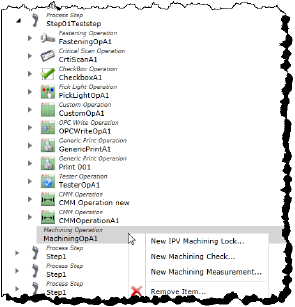
The dialog for naming the component type you selected opens.
5.Type a name for the new component.
6.Click Next. The dialog for configuring the attributes of your new component opens.
You can use the following table to reference the list of your component’s attributes and descriptions of their purposes, if required.
Table 72: Component attribute lookup links
|
|
7.When you have completed configuring the attributes, click Finish. The new component is displayed in the Process Step’s folder.
Editing Existing Components
To edit an existing Machining Operation or the components associated with it, follow these steps.
1.If you are not already in the SmartBuild interface, click on the Portal > SmartBuild button. The SmartBuild interface opens.
2.On the SmartBuild panel, select Advanced. The Advanced workspace opens.
3.Expand the Process Steps hierarchy to view the Machining Operations. Optionally, expand its hierarchy to access any subcomponents necessary. Locate the component whose attributes you want to edit.
4.Select the component. Its attributes populate the Details pane.
5.Make the changes you require to the component’s attributes.
You can use the following table to reference the list of your component’s attributes and descriptions of their purposes, if required.
Table 73: Component attribute lookup links
6.When you have completed configuring the attributes, click Save. The component’s updated attributes are applied.
Process Steps — OPC Write Operation
The OPC Write Operations folder gathers and makes available for editing the OPC Write Operations of a Process Step.
An OPC Write Operation allows you to send a predetermined value to a PLC upon entering a step. This can be used to tell the PLC that the operator is on a specific step or to send other data such as the amount of oil to fill for the product that is loaded.
Creating New OPC Write Operations for Process Steps
To create a new OPC Write Operation for a Process Step, follow these steps.
1.If you are not already in the SmartBuild interface, click on the Portal > SmartBuild button. The SmartBuild interface opens.
2.On the SmartBuild panel, select Advanced. The Advanced workspace opens.
3.Expand the Process Steps folder and locate the Process Step for which you want to create a new OPC Write Operation.
4.Right-click the Process Steps icon and select New > OPC Write Operation.
Figure 279: Process Step Operation menu

The dialog for naming the OPC Write Operation opens.
5.Type a name for the new OPC Write Operation.
6.Click Next. The dialog for configuring the attributes of your new OPC Write Operation opens.
7.Configure the following attributes:
Refer to the table Heading3.
8.When you have completed configuring the attributes, click Finish. The new component is displayed in the Process Step’s folder.
Editing Existing OPC Write Operations
To edit an existing OPC Write Operation, follow these steps.
1.If you are not already in the SmartBuild interface, click on the Portal > SmartBuild button. The SmartBuild interface opens.
2.On the SmartBuild panel, select Advanced. The Advanced workspace opens.
3.Expand the Process Steps hierarchy to view the OPC Write Operations.
4.Select the OPC Write Operation. Its attributes populate the Details pane.
5.Make the changes you require to the component’s attributes.
Refer to the table Heading3.
6.When you have completed configuring the attributes, click Save. The component’s updated attributes are applied.
Process Steps — Pick Light Operation
The Pick Light Operations folder gathers and makes available for editing the Pick Light Operations of a Process Step. It also enables you to create the sub-components related to them.
A Pick Light Operation is used to ensure that an operator selects the right part(s), in the right quantity, at the right step of the production process.
Creating New Pick Light Operations for Process Steps
To create a new Pick Light Operation for a Process Step, follow these steps.
1.If you are not already in the SmartBuild interface, click on the Portal > SmartBuild button. The SmartBuild interface opens.
2.On the SmartBuild panel, select Advanced. The Advanced workspace opens.
3.Expand the Process Steps folder and locate the Process Step for which you want to create a new Pick Light Operation.
4.Right-click the Process Steps icon and select New > Pick Light Operation.
Figure 280: Process Step Operation menu

The dialog for naming the Pick Light Operation opens.
5.Type a name for the new Pick Light Operation.
6.Click Next. The dialog for configuring the attributes of your new Pick Light Operation opens.
7.Configure the following attributes:
Refer to the table Heading3.
8.When you have completed configuring the attributes, click Finish. The new component is displayed in the Process Step’s folder.
Creating a New Pick Light Input Source for Pick Light Operations
To create a new Pick Light Input Source for a Pick Light Operation, follow these steps.
1.If you are not already in the SmartBuild interface, click on the Portal > SmartBuild button. The SmartBuild interface opens.
2.On the SmartBuild panel, select Advanced. The Advanced workspace opens.
3.Expand the Process Steps folder and locate the Pick Light Operation to which you want to add a component.
4.Right-click the Pick Light Operation and select New Pick Light Input Source....
Figure 281: Pick Light Operation menu

The dialog for naming the new Pick Light Input Source opens.
5.Type a name for the new Pick Light Input Source.
6.Click Next. The dialog for configuring the attributes of your new component opens.
Refer to the table Heading3.
7.When you have completed configuring the attributes, click Finish. The new component is displayed in the Process Step’s folder.
Editing Existing Components
To edit an existing Pick Light Operation or the components associated with it, follow these steps.
1.If you are not already in the SmartBuild interface, click on the Portal > SmartBuild button. The SmartBuild interface opens.
2.On the SmartBuild panel, select Advanced. The Advanced workspace opens.
3.Expand the Process Steps hierarchy to view the Pick Light Operations. Optionally, expand its hierarchy to access any subcomponents necessary. Locate the component whose attributes you want to edit.
4.Select the component. Its attributes populate the Details pane.
5.Make the changes you require to the component’s attributes.
You can use the following table to reference the list of your component’s attributes and descriptions of their purposes, if required.
Table 74: Component attribute lookup links
6.When you have completed configuring the attributes, click Save. The component’s updated attributes are applied.
Process Steps — Tester Operation
The Tester Operations folder gathers and makes available for editing the Tester Operations of a Process Step. It also enables you to create the sub-components related to them.
Creating New Tester Operations for Process Steps
To create a new Tester Operation for a Process Step, follow these steps.
1.If you are not already in the SmartBuild interface, click on the Portal > SmartBuild button. The SmartBuild interface opens.
2.On the SmartBuild panel, select Advanced. The Advanced workspace opens.
3.Expand the Process Steps folder and locate the Process Step for which you want to create a new Tester Operation.
4.Right-click the Process Steps icon and select New > Tester Operation.
Figure 282: Process Step Operation menu

The dialog for naming the Tester Operation opens.
5.Type a name for the new Tester Operation.
6.Click Next. The dialog for configuring the attributes of your new Tester Operation opens.
7.Configure the following attributes:
Refer to the table Heading3.
8.When you have completed configuring the attributes, click Finish. The new component is displayed in the Process Step’s folder.
Creating New Sub-components for Tester Operations
Sub-components can be added to a Tester Operation. To create a new component for a Tester Operation, follow these steps.
1.If you are not already in the SmartBuild interface, click on the Portal > SmartBuild button. The SmartBuild interface opens.
2.On the SmartBuild panel, select Advanced. The Advanced workspace opens.
3.Expand the Process Steps folder and locate the Tester Operation to which you want to add a component.
4.Right-click the Tester Operation and select the component you want to create.
Figure 283: Tester Operation menu
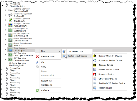
The dialog for naming the component type you selected opens.
5.Type a name for the new component.
6.Click Next. The dialog for configuring the attributes of your new component opens.
You can use the following table to reference the list of your component’s attributes and descriptions of their purposes, if required.
Table 75: Component attribute lookup links
|
|
7.When you have completed configuring the attributes, click Finish. The new component is displayed in the Process Step’s folder.
Editing Existing Components
To edit an existing Tester Operation or the components associated with it, follow these steps.
1.If you are not already in the SmartBuild interface, click on the Portal > SmartBuild button. The SmartBuild interface opens.
2.On the SmartBuild panel, select Advanced. The Advanced workspace opens.
3.Expand the Process Steps hierarchy to view the Tester Operations. Optionally, expand its hierarchy to access any subcomponents necessary. Locate the component whose attributes you want to edit.
4.Select the component. Its attributes populate the Details pane.
5.Make the changes you require to the component’s attributes.
You can use the following table to reference the list of your component’s attributes and descriptions of their purposes, if required.
Table 76: Component attribute lookup links
6.When you have completed configuring the attributes, click Save. The component’s updated attributes are applied.
Process Steps — Trigger Operation
The Trigger Operations folder gathers and makes available for editing the Trigger Operations of a Process Step. It also enables you to create the OPC Tag Item Input Sources related to them.
A Trigger Operation provides the ability for an operator to initiate a manual start signal. The start signal can be used internally by PINpoint software or by third party systems. In the case of PINpoint software, the start signal can be used to initiate the calling of a custom extension (*.dll). In the case of third party systems, the start signal can be used by the operator to initiate the execution of custom PLC code. While on the surface it may appear that PINpoint Software already has this functionality with established operations (e.g. Scan OP and Check box OP), and in many operational scenarios the established functionality is sufficient, there are operational scenarios where the established operations have limitations. The objective of the Trigger Operation is to create an operation which must be satisfied as part of the error-proofing process which can generate a momentary start signal which can be triggered multiple times.
Creating New Trigger Operations for Process Steps
To create a new Trigger Operation for a Process Step, follow these steps.
1.If you are not already in the SmartBuild interface, click on the Portal > SmartBuild button. The SmartBuild interface opens.
2.On the SmartBuild panel, select Advanced. The Advanced workspace opens.
3.Expand the Process Steps folder and locate the Process Step for which you want to create a new Trigger Operation.
4.Right-click the Process Steps icon and select New > Trigger Operation.
Figure 284: Process Step Operation menu

The dialog for naming the Trigger Operation opens.
5.Type a name for the new Trigger Operation.
6.Click Next. The dialog for configuring the attributes of your new Trigger Operation opens.
7.Configure the following attributes:
Refer to the table Heading3.
8.When you have completed configuring the attributes, click Finish. The new component is displayed in the Process Step’s folder.
Creating a New OPC Tag Item Input Source for Trigger Operations
To create a new OPC Tag Item Input Source for a Trigger Operation, follow these steps.
1.If you are not already in the SmartBuild interface, click on the Portal > SmartBuild button. The SmartBuild interface opens.
2.On the SmartBuild panel, select Advanced. The Advanced workspace opens.
3.Expand the Process Steps folder and locate the Trigger Operation to which you want to add a component.
4.Right-click the Trigger Operation and select New OPC Tag Item Input Source....
Figure 285: Trigger Operation menu
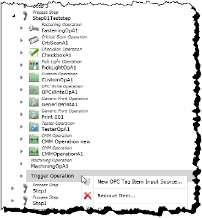
The dialog for naming the new OPC Tag Item Input Source opens.
5.Type a name for the new OPC Tag Item Input Source.
6.Click Next. The dialog for configuring the attributes of your new component opens.
Refer to the table Heading3.
7.When you have completed configuring the attributes, click Finish. The new component is displayed in the Process Step’s folder.
Editing Existing Components
To edit an existing Trigger Operation or the components associated with it, follow these steps.
1.If you are not already in the SmartBuild interface, click on the Portal > SmartBuild button. The SmartBuild interface opens.
2.On the SmartBuild panel, select Advanced. The Advanced workspace opens.
3.Expand the Process Steps hierarchy to view the Trigger Operations. Optionally, expand its hierarchy to access any subcomponents necessary. Locate the component whose attributes you want to edit.
4.Select the component. Its attributes populate the Details pane.
5.Make the changes you require to the component’s attributes.
You can use the following table to reference the list of your component’s attributes and descriptions of their purposes, if required.
Table 77: Component attribute lookup links
6.When you have completed configuring the attributes, click Save. The component’s updated attributes are applied.
Products Folder
The Products folder gathers all the Products that currently exist in your instance of PINpoint. As well, it enables you to edit the attributes of those products, and create new products for the system and the sub-components related to them.
Figure 286: Devices folder hierarchy

Creating a New Product
To create a new Product, follow these steps.
1.If you are not already in the SmartBuild interface, click on the Portal > SmartBuild button. The SmartBuild interface opens.
2.On the SmartBuild panel, select Advanced. The Advanced workspace opens.
3.Right-click the Products icon and select New Product....
Figure 287: Products menu
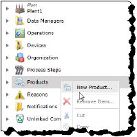
The dialog for naming the new Product opens.
4.Type a name for the new Product.
5.Click Next. The dialog for configuring the attributes of your new component opens.
Refer to the table Heading3.
6.When you have completed configuring the attributes, click Finish. The new Product is displayed in the Products folder.
Creating New Sub-components to Products
Sub-components can be added to Products. To create a new component for a Product, follow these steps.
1.If you are not already in the SmartBuild interface, click on the Portal > SmartBuild button. The SmartBuild interface opens.
2.On the SmartBuild panel, select Advanced. The Advanced workspace opens.
3.Expand the Products hierarchy.
4.Right-click the Product to which you want to add a component and select the component you want to create.
Figure 288: Product menu

The dialog for naming the component type you selected opens.
5.Type a name for the new component.
6.Click Next. The dialog for configuring the attributes of your new component opens.
You can use the following table to reference the list of your component’s attributes and descriptions of their purposes, if required.
Table 78: Component attribute lookup links
7.When you have completed configuring the attributes, click Finish. The new component is displayed in the Products folder.
Creating New Sub-components to Steps
Sub-components can be added to Process Steps in the Product’s hierarchy. In addition, Process Steps themselves can be added to Decision Branch Steps by right-clicking the Decision Branch Step and selecting New Process Step....
To add sub-components to the Process Steps of a Product, expand the Product hierarchy to view the Process Step to which you want to add a new component and right-click it to access the menu of components you can add to it.
Figure 289: Process Step menu

Editing Existing Components
To edit existing components organized in the Products hierarchy, follow these steps.
1.If you are not already in the SmartBuild interface, click on the Portal > SmartBuild button. The SmartBuild interface opens.
2.On the SmartBuild panel, select Advanced. The Advanced workspace opens.
3.Expand the Products hierarchy, and those of any subcomponents necessary, and locate the component whose attributes you want to edit.
4.Select the component. Its attributes populate the Details pane.
5.Make the changes you require to the component’s attributes.
You can use the following table to reference the list of your component’s attributes and descriptions of their purposes, if required.
Table 79: Component attribute lookup links
6.When you have completed configuring the attributes, click Save. The component’s updated attributes are applied.
The Reasons folder contains the lists of Reasons available in the PINpoint system. It enables you to create new categories for Reasons, and to create new Reasons of different types within them:
•Listbox Item: for general production issues
•Tool Lock Reason: for instances when tools are locked under the use of an operator
Reasons are sets of explanations used to explain the use of an override command. They are also used in Reporting to categorize lost production time.
Figure 290: Reasons hierarchy
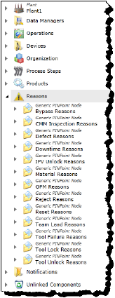
Creating a New Generic PINpoint Node (Reasons Folder)
Creating a new Reasons category is called, in PINpoint, creating a new Generic PINpoint Node. To do so, follow these steps.
1.If you are not already in the SmartBuild interface, click on the Portal > SmartBuild button. The SmartBuild interface opens.
2.On the SmartBuild panel, select Advanced. The Advanced workspace opens.
3.Right-click the Reasons icon and select New Generic PINpoint Node....
Figure 291: Reasons menu

The dialog for naming the new Node (Reasons category) opens.
4.Type a name for the new Node.
5.Click Next. The dialog for configuring the attributes of your new component opens.
|
Attribute |
Description |
Data Type |
Input Type |
|---|---|---|---|
|
Node Name |
The report database name. Used if a different name on the report is required. |
Text |
Text Box |
|
SortOrder |
The order of item in PINpoint. If this value is changed, the user must refresh SmartBuild before changes are reflected. |
Number |
Counter Box |
6.When you have completed configuring the attributes, click Finish. The new Node is displayed in the Reasons folder.
Creating a New Reason
Reasons are created in the Nodes (Reasons category folder). To create a new Reason, follow these steps.
1.If you are not already in the SmartBuild interface, click on the Portal > SmartBuild button. The SmartBuild interface opens.
2.On the SmartBuild panel, select Advanced. The Advanced workspace opens.
3.Expand the Reasons hierarchy.
4.Right-click the Node (Reasons category folder) to which you want to add a new Reason and select the type of reason you want to create.
Figure 292: Node menu
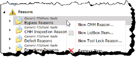
The dialog for naming the component type you selected opens.
5.Type a name for the new component.
6.Click Next. The dialog for configuring the attributes of your new component opens.
You can use the following table to reference the list of your component’s attributes and descriptions of their purposes, if required.
Table 80: Component attribute lookup links
7.When you have completed configuring the attributes, click Finish. The new component is displayed in the Products folder.
To remove a new Reason, follow these steps.
1.If you are not already in the SmartBuild interface, click on the Portal > SmartBuild button. The SmartBuild interface opens.
2.On the SmartBuild panel, select Advanced. The Advanced workspace opens.
3.Expand the Reasons hierarchy.
4.Expand the Reason category folder that contains the Reason you want to remove.
5.Select the Reason you want to remove and right-click it.
6.Select Permanently Remove Items... from the menu.
7.When asked to confirm the deletion, click OK.
Editing Existing Components
To edit existing Nodes (Reasons category folders) or their Reasons, follow these steps.
1.If you are not already in the SmartBuild interface, click on the Portal > SmartBuild button. The SmartBuild interface opens.
2.On the SmartBuild panel, select Advanced. The Advanced workspace opens.
3.Expand the Reasons hierarchy, and those of any Nodes necessary, and locate the Node or Reason whose attributes you want to edit.
4.Select the component. Its attributes populate the Details pane.
5.Make the changes you require to the component’s attributes.
You can use the following table to reference the list of your component’s attributes and descriptions of their purposes, if required.
Table 81: Component attribute lookup links
|
|
6.When you have completed configuring the attributes, click Save. The component’s updated attributes are applied.
Notifications Folder
The Notifications folder gathers together all the Notifications existing in the PINpoint system in their appropriate categories and makes them available for viewing and editing. While Notifications themselves cannot be created in the Notifications folder itself (they are created in Heading2), in some instance, sub-components can be created for the components found in the Notifications folder.
The categories of Notifications are as follows:
•External Destination Notifications: Gathers the External Destination Actions and the Notifications designated to each.
•Email Notifications: Gathers the Email Actions used to send emails to particular recipients, and the Notifications designated to each.
•Text Message Notifications: Gathers the Text Actions used to send text messages to particular recipients, and the Notifications designated to each.
•Sound Notifications: Gathers the Sound Actions used to produce sound alerts on the production line, and the Notifications designated to each.
•Stack Light Notifications: Gathers the Stack Light Actions used to produce Andon light alerts on the production line, and the Notifications designated to each.
•BigScreen Notifications: Gathers the BigScreen Actions used to visual alerts, Gauges, and Station Events on BigScreens, and the Notifications designated to each.
Notifications are for sending information about Events to operators, managers, and other people required to know about them, by means of a variety of different methods.
Figure 293: Notifications hierarchy
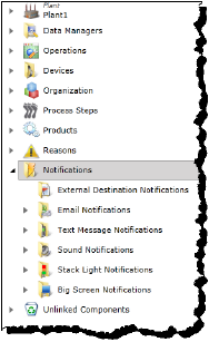
Editing Existing Components
To edit existing components organized in the Products hierarchy, follow these steps.
1.If you are not already in the SmartBuild interface, click on the Portal > SmartBuild button. The SmartBuild interface opens.
2.On the SmartBuild panel, select Advanced. The Advanced workspace opens.
3.Expand the Notifications hierarchy, and those of any subcomponents necessary, and locate the component whose attributes you want to edit.
4.Select the component. Its attributes populate the Details pane.
5.Make the changes you require to the component’s attributes.
You can use the following table to reference the list of your component’s attributes and descriptions of their purposes, if required.
Table 82: Component attribute lookup links
6.When you have completed configuring the attributes, click Save. The component’s updated attributes are applied.
Creating New Sub-components for BigScreens
To create a new component for a BigScreen, follow these steps.
1.If you are not already in the SmartBuild interface, click on the Portal > SmartBuild button. The SmartBuild interface opens.
2.On the SmartBuild panel, select Advanced. The Advanced workspace opens.
3.Expand the Notifications hierarchy.
4.Expand the BigScreen Notifications hierarchy and locate the BigScreen you want to work with.
5.Right-click the BigScreen icon and hover the mouse pointer over New to view the options. Select the component you want to create.
Figure 294: BigScreen menu New component type options

The dialog for naming the component type you selected opens.
6.Type a name for the new component.
7.Click Next. The dialog for configuring the attributes of your new component opens.
You can use the following table to reference the list of your component’s attributes and descriptions of their purposes, if required.
Table 83: Component attribute lookup links
8.When you have completed configuring the attributes, click Finish. The new component is displayed in the BigScreen’s folder.
The Unlinked Components folder gathers together all the components existing in the PINpoint system in their appropriate categories and makes them available for viewing and editing. In some cases, sub-components can be created for the components in the Unlinked Components folder.
Unlinked components are those that are orphaned in the PINpoint system and do not have a parent relationship integrating them into a production line. This is to say that these components remain configured and are available to be used in the PINpoint system, but are not currently being used in it.
Figure 295: Unlinked Components hierarchy
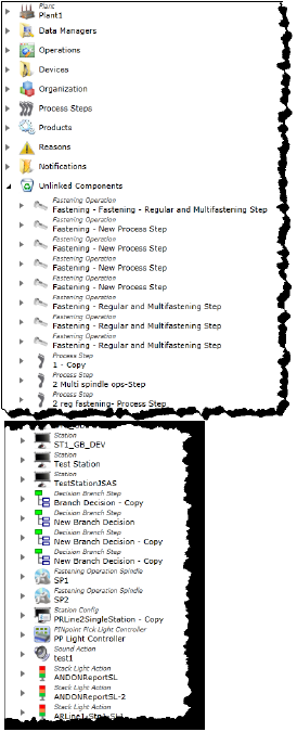
Linking Unlinked Components
Unlinked components are available for use by the appropriate parent component. If you want to make use of an unlinked component by adding it to a parent component, follow these steps.
1.If you are not already in the SmartBuild interface, click on the Portal > SmartBuild button. The SmartBuild interface opens.
2.On the SmartBuild panel, select Advanced. The Advanced workspace opens.
3.Expand the Unlinked Components hierarchy and locate the component you want to link to a parent component.
Figure 296: Select unlinked component
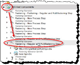
4.Select the component. Its attributes populate the Details pane.
5.Select the Relations pane. The relationships of the component are displayed.
Figure 297: Unlinked components’s relations

6.In the Relations pane, right-click the component and select Add Parent(s). The Add New Relationships dialog opens.
Figure 298: Select Add Parent(s)
_1.png)
7.Expanding the hierarchy of the appropriate categories. Appropriate parent components are designated by the appearance of check boxes beside them.
Figure 299: Appropriate parent component choices

8.Select the component or components you want to designate as the parent or parents of the unlinked component by filling the check box of each.
Figure 300: New parent components selected

9.Click Next.
10.When asked to confirm the new relationship(s), click Finish.
The new relationships are displayed in the Relations tab. Note that the sub-components of the component are also included in the new parent-child relationship(s).
Figure 301: New relationships
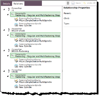
Refreshing the Unlinked Components folder will confirm that the previously unlinked component is no longer in the Unlinked Components hierarchy.
Figure 302: Refresh Unlinked Components
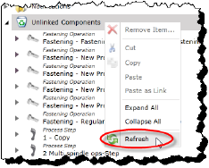
Editing Existing Components
To edit existing Nodes (Reasons category folders) or their Reasons, follow these steps.
1.If you are not already in the SmartBuild interface, click on the Portal > SmartBuild button. The SmartBuild interface opens.
2.On the SmartBuild panel, select Advanced. The Advanced workspace opens.
3.Expand the Unlinked Components hierarchy, and those of any components necessary, and locate the component whose attributes you want to edit.
4.Select the component. Its attributes populate the Details pane.
5.Make the changes you require to the component’s attributes.
6.When you have completed configuring the attributes, click Save. The component’s updated attributes are applied.